
Multifunctional filling valve

a multi-functional, filling valve technology, applied in the field of filling valves, can solve the problems of complex system design and process sequence, affecting the hygienic effect of the product, and limiting the use of volumetric metering methods, etc., to achieve the effect of improving the hygienic

Active Publication Date: 2021-01-14
KRONES AG
View PDF3 Cites 1 Cited by
  • Summary
  • Abstract
  • Description
  • Claims
  • Application Information

AI Technical Summary

Benefits of technology

The patent describes an improved filling valve that is designed to improve hygiene and prevent contamination when changing products frequently. The valve is compact and reliable.

Problems solved by technology

The use of separate metering stations for a plurality of components, however, leads to a complex system design and process sequence since the filling of each container is divided between a plurality of separate metering / filling stations at which the container has to be positioned for the duration of the respective metering times. Whilst it is possible, in principle, to meter the plurality of components into the containers via separate lines and discharge openings simultaneously and at a common filling station, this is restricted by the size of the bottle opening and / or container opening.
Other volumetric metering methods, such as for example the use of pumps or timed / pressurized filling, often have greater instability and tend to react more sensitively to changes in the metering medium, for example to changes in the pressure, temperature or composition.
This results in frequent calibration, in particular when changing the metering medium.
It is almost impossible to implement a gravimetric measurement of the metered amounts due to significant differences between the metering weight, in the case of tiny quantities (μl), and the container weight.
The late mixing, however, is also associated with technical difficulties.
Thus an optimization of the duration of the filling process is not possible in a simple manner since the metering process may not be accelerated as desired, for example, by using a flowmeter.
It should be added that the later mixing is associated with a structural complexity which is not inconsiderable.
In the case of small container openings, it is only possible with difficulty to fill a moving container with a stationary metering head.
If a plurality of different metered components are intended to be provided at the same time, both solutions are complex in terms of engineering technology, cost-intensive and maintenance-intensive and require a large amount of constructional space, due to the plurality of filling points and / or metered components on the filling valve.
Those metering techniques which determine the volume and convey the medium at the same time, namely by means of pumps or piston metering pumps, have the drawback that it is not possible to provide any feedback to the controller about the volume specifically introduced into the container.
Filling valves with swirl bodies, however, have a drawback that it is only possible to remove migrated filling product, in particular any metered components, with difficulty.
The swirl generation, however, counteracts such a thorough cleaning.
However, in laminar flows it is almost impossible for transverse mixing to take place, which could be important for thorough flushing out.
A further technical problem in the above-described swirl valves is that these swirl valves do not provide a stepless control function of the flow rate and thus are not suitable for the high output filling machines which are currently available, in particular with flexible metering by displacement to the rear.
The use of two control members in series—shut-off and flow control—is complex in terms of construction and increases the pressure loss.
Currently, a wide variety of different types of filling valve exists for different application purposes (carbonated or still filling products, with or without pieces, glass containers or PET containers, etc.) This leads to significant effort in terms of care and maintenance and many machine variants.

Method used


Image

  • Multifunctional filling valve
  • Multifunctional filling valve
  • Multifunctional filling valve

Examples


Embodiment Construction

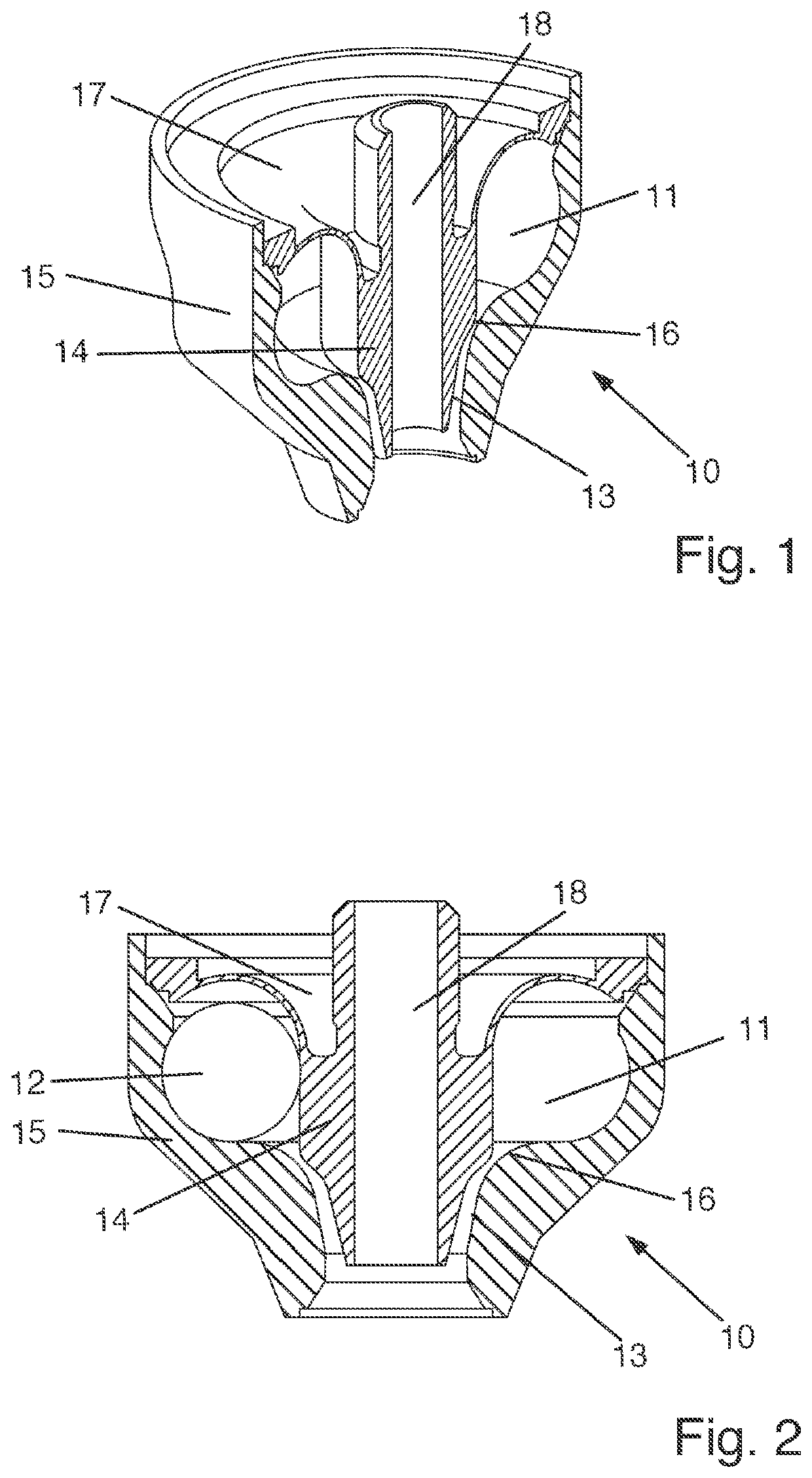
[0068]Exemplary embodiments are described hereinafter with reference to the figures. In this case, elements which are the same, similar or similar-acting are provided with identical reference numerals in the figures and a repeated description of these elements is dispensed with in some cases in order to avoid redundancies.

[0069]FIG. 1 is a perspective view of the valve base body 10 of a filling valve 1 (see FIG. 6) with swirl generation. FIG. 2 shows the valve base body 10 in a cross-sectional view.

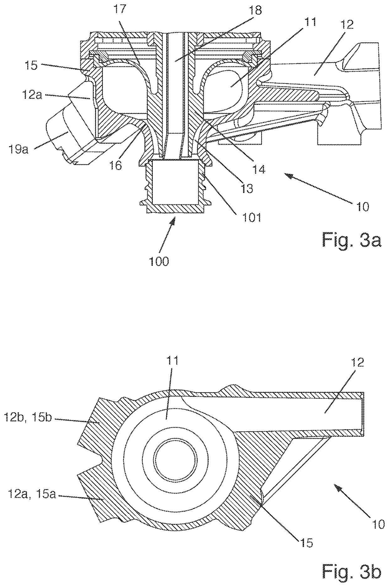
[0070]The valve base body 10 has a swirl chamber 11 designed as an annular duct and / or torus. The valve base body 10 also has a main inlet 12, not visible in the perspective view in FIG. 1, which opens tangentially or substantially tangentially into the swirl chamber 11. The main inlet 12 is shown schematically in FIG. 2. The main inlet 12 is additionally shown in the exemplary embodiments of FIGS. 2, 3a, 3b and others.

[0071]In the lower region of the valve base body 10 the swirl chamber ...


PUM


Abstract

A filling valve for filling a container with a filling product, e.g., a beverage in a beverage filling system, includes a valve base body. The valve base body includes an outlet configured to discharge the filling product into the container; a swirl chamber configured to receive the filling product and is able to be brought into a fluidic connection with the outlet; and a main inlet, which feeds into the swirl chamber and is configured to introduce at least one main component of the filling product into the swirl chamber such that the filling product is swirled in the swirl chamber, whereby after exiting from the outlet the filling product flows downwardly in a spiral movement in the container. The swirl chamber has an annular shape, the cross-sectional contour thereof having a rounded shape, substantially without corner points, in the direction of extent and perpendicular to the direction of extent.

Description

CROSS REFERENCE TO RELATED APPLICATIONS[0001]This application claims priority from German Patent Application No. DE 10 2019 118 937.3, filed on Jul. 12, 2019 in the German Patent and Trademark Office, the disclosure of which is incorporated herein by reference in its entirety.BACKGROUNDTechnical Field[0002]The present invention relates to a filling valve for filling a container with a filling product, for example, a beverage in a beverage filling system.Related Art[0003]In order to mix and to fill filling products consisting of a plurality of components, various technologies for metering the individual components are known and are set forth briefly hereinafter:[0004]Thus the desired components may be individually metered and filled, for example, via separate metering stations, as is disclosed for example in US 2008 / 0271809 A1. The use of separate metering stations for a plurality of components, however, leads to a complex system design and process sequence since the filling of each ...

Claims


Application Information

Patent Timeline
IPC IPC(8): B67D7/02B67D7/32
CPCB67D7/0294B67D7/3281B67C3/26B67C3/026B67C3/281B67C2003/268
Inventor BECHER, VALENTINHENGL, BENEDIKTDOBLINGER, JOSEFHUBER, ANTONAUER, HUBERTPOESCHL, STEFAN
Owner KRONES AG
Learn More