
Culture Vessel and Cell Culture Device

Pending Publication Date: 2021-01-07
SUMITOMO BAKELITE CO LTD +1
View PDF7 Cites 0 Cited by
  • Summary
  • Abstract
  • Description
  • Claims
  • Application Information

AI Technical Summary

Benefits of technology

This patent describes a configuration for a culture vessel that reduces foam when a common nozzle is used to supply both liquid culture medium and gas. The nozzle can be placed at different locations in the vessel, which allows for softening impacts when loading the culture medium and suppressing foam caused by the gas. The gas can also be fed into the vessel from the top, while the culture medium is fed from the bottom to prevent foam caused by the gas. This configuration simplifies the device and reduces the risk of foaming in the culture medium.

Problems solved by technology

In this case, when supplying the culture medium, the culture medium may foam due to impacts when dripping.
However, even in this case, when a tip portion of the nozzle is immersed under the liquid surface of the culture medium, the gas is supplied below the liquid surface, so foaming of the culture medium occurs.

Method used


Image

  • Culture Vessel and Cell Culture Device
  • Culture Vessel and Cell Culture Device
  • Culture Vessel and Cell Culture Device

Examples


first embodiment

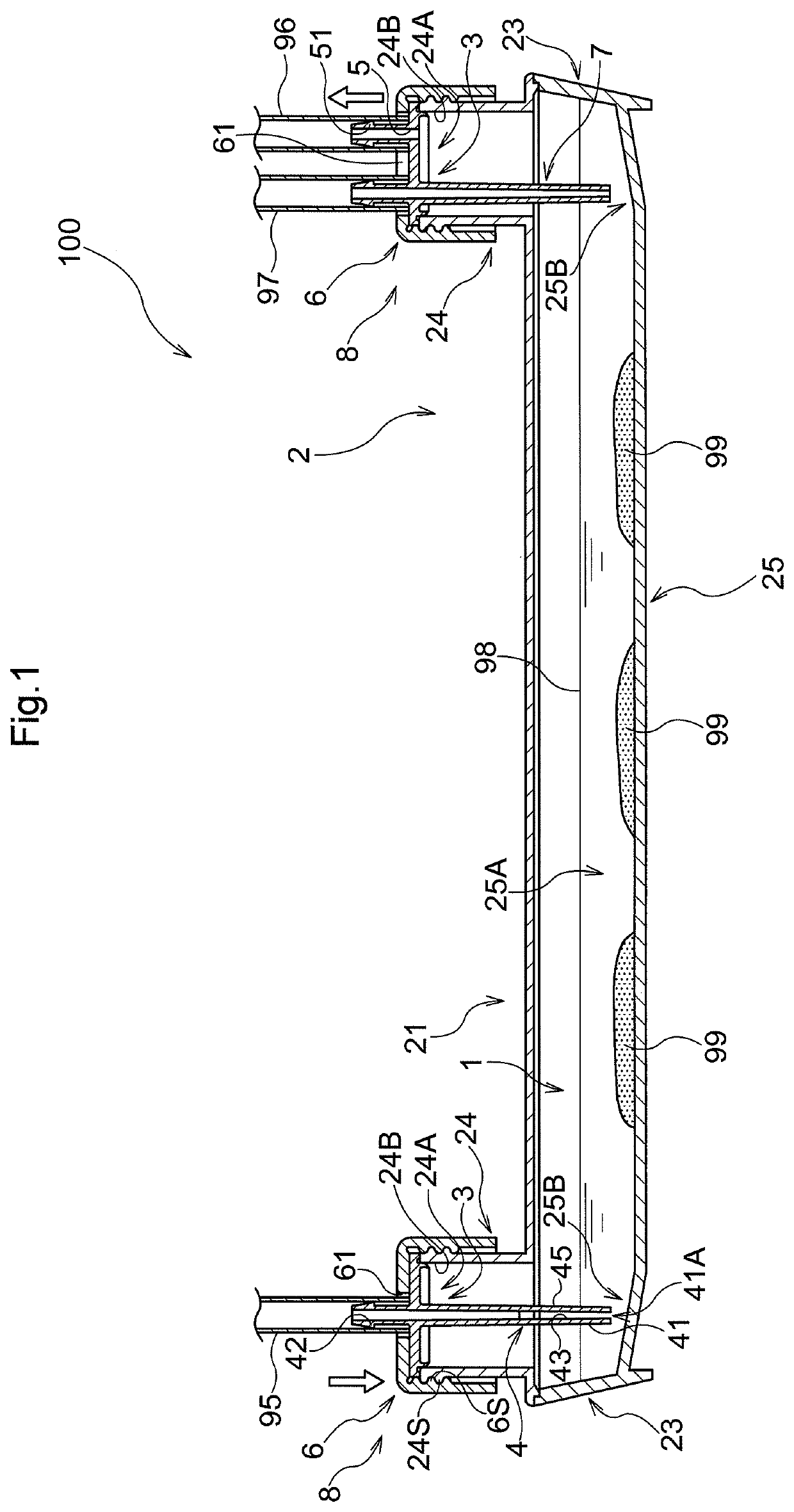
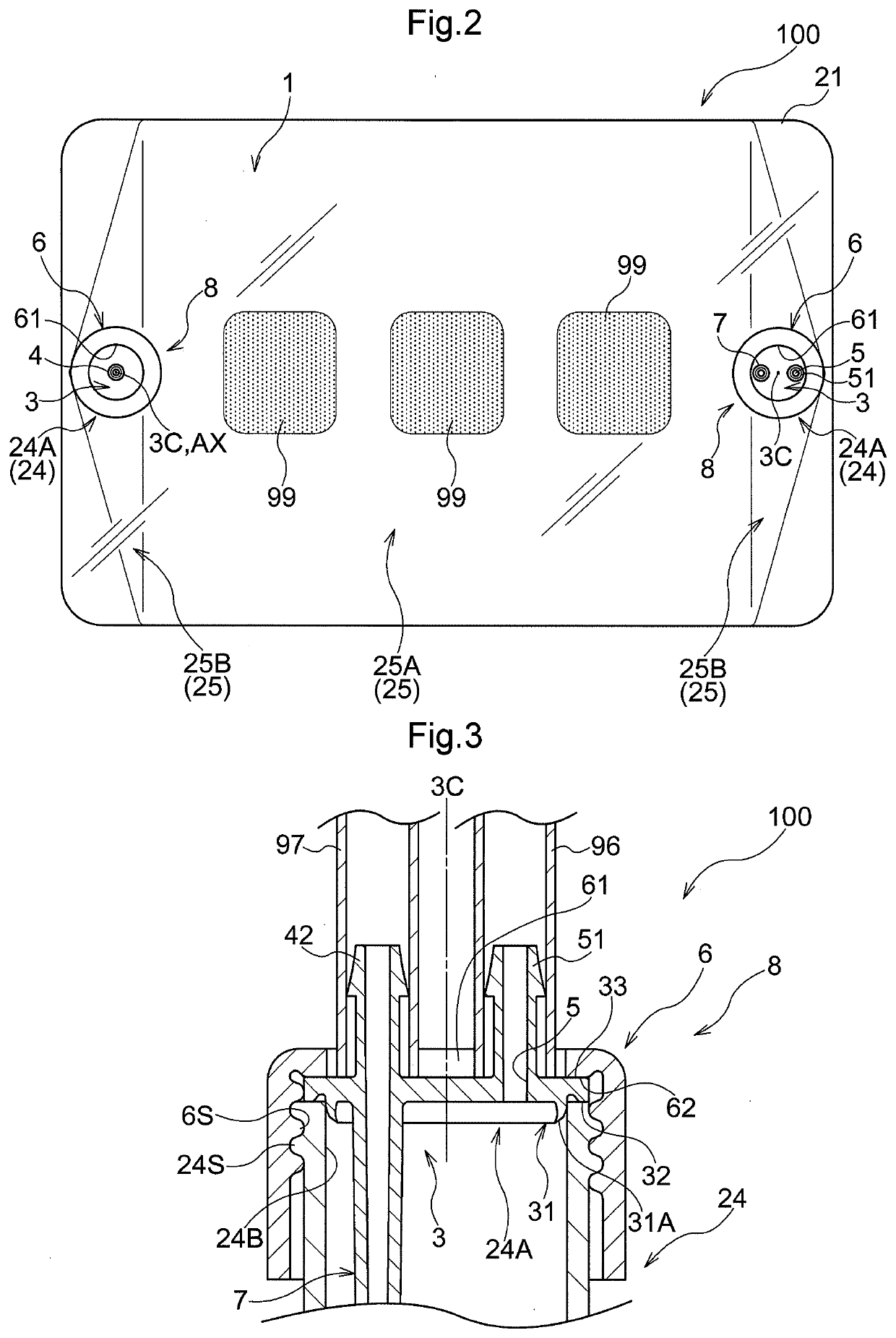
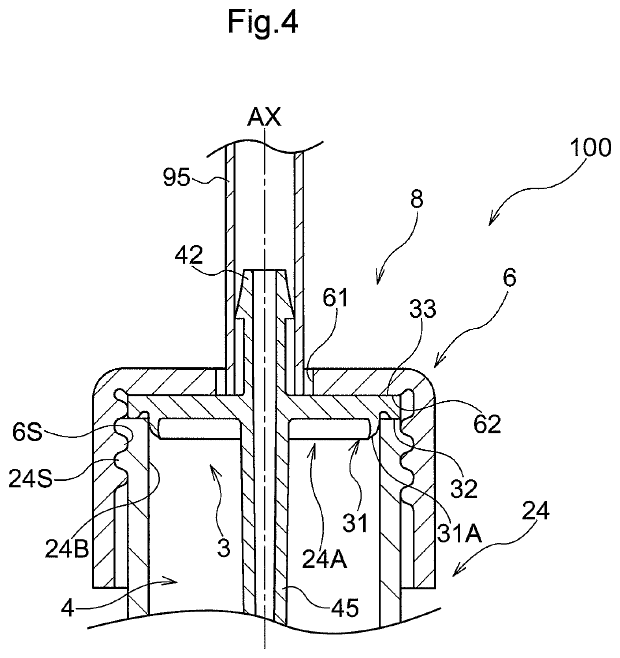
[0054]A first embodiment of a culture vessel will be described with reference to the drawings. As shown in FIG. 1, a culture vessel 100 has a housing space 1 inside and is used to culture cells 99 within the housing space 1. The housing space 1 houses the cells 99 and a culture medium 98 for supplying nutrients to the cells 99. The components of the culture medium 98 can be appropriately changed depending on the purpose of the culture. Further, a liquid culture medium (including a semi-liquid culture medium or the like) can be used as the culture medium 98. In the present embodiment, a liquid culture medium having high fluidity is used as the culture medium 98.

[0055]The culture vessel 100 includes a vessel body 2 having an opening portion 24A that communicates with the housing space 1, and a lid 8 that closes the opening portion 24A. By closing the opening portion 24A with the lid 8, airtightness of the housing space 1 can be secured. In the present embodiment, the lid 8 includes an...

second embodiment

[0093]Next, a second embodiment of the culture vessel 100 will be described with reference to FIGS. 8 and 9. Below, the culture vessel 100 according to the present embodiment will be described focusing mainly on differences from the above-described first embodiment. Note that points that are not particularly described are the same as in the above-described first embodiment.

[0094]As shown in FIGS. 8 and 9, the supply nozzle 4 has a rib portion 44 protruding toward the axial center AX of the supply nozzle 4 on the inner face of the side wall 45 of the supply nozzle 4. The culture medium 98 flowing down the inside of the supply nozzle 4 flows through the rib portion 44 by the action of the surface tension occurring between the culture medium 98 and the rib portion 44. The rib portion 44 allows the culture medium 98 to flow through the inside of the supply nozzle 4 so as to avoid the vent opening portion 43, so the culture medium 98 can smoothly reach the tip opening portion 41A. Also, ...


PUM


Abstract

A culture vessel that can suppress foaming in a culture medium when a common nozzle is used to supply a liquid culture medium and a gas together. This culture vessel includes: a vessel body having an opening portion that communicates with a housing space; a lid that closes the opening portion; and a nozzle that passes through the and extends to the housing space, and supplies a liquid culture medium and a gas together. The nozzle has a vent opening portion that is formed so as to open in a side of the nozzle and serves as a movement path of the gas from inside of the nozzle into the housing space.

Description

TECHNICAL FIELD[0001]The present invention relates to a culture vessel and a cell culture device for culturing cells within a housing space.BACKGROUND ART[0002]The culture vessel is supplied with a culture medium (liquid culture medium) that serves as a cell growth environment, and a gas (carbon dioxide) for appropriately maintaining the growth environment. An example of such a culture vessel is disclosed in Patent Document 1 (JP 2006-204263A) described below. As shown in FIG. 7 of Patent Document 1, a culture vessel 30′ is provided with an opening portion 38 to which a tube 40 for supplying a culture medium B is connected. The culture medium B is supplied from the opening portion 38 to a housing space of the culture vessel 30′. Then, the gas G is supplied from an opening portion 36 provided at a different location than the opening portion 38 for supplying the culture medium B.[0003]Here, from the viewpoint of reducing the cost of the device that is the supply source of the culture ...

Claims


Application Information

Patent Timeline
IPC IPC(8): C12M1/00C12M1/12
CPCC12M29/06C12M23/38C12M23/06C12M29/20C12M23/04
Inventor TSUKADA, RYOHEIYAKABE, TORUOKUBO, HARUOKIYAMA, MASAHARUKATO, MIDORISAITO, HIKARU
Owner SUMITOMO BAKELITE CO LTD
Learn More