
Electric motor

a technology of electric motors and motors, applied in the direction of electrical equipment, dynamo-electric machines, supports/enclosements/casings, etc., can solve the problems of undesirable acoustic characteristics of motors, and achieve the effects of improving acoustic characteristics, improving airflow characteristics, and improving efficiency of electric motors

Pending Publication Date: 2020-12-31
DYSON TECH LTD
View PDF4 Cites 0 Cited by
  • Summary
  • Abstract
  • Description
  • Claims
  • Application Information

AI Technical Summary

Benefits of technology

The present invention concerns an electric motor that has improved acoustic characteristics. The motor has a soft-mounted bearing, which prevents vibrations from being transferred between the bearing and the frame, resulting in less noise. The motor also has a stator assembly that is soft-mounted to the frame, which also prevents vibrations from being transferred between the stator assembly and the frame. This results in a quieter and more desirable motor.

Problems solved by technology

When operating at such high speeds, the motor may have undesirable acoustic characteristics.

Method used


Image

  • Electric motor
  • Electric motor
  • Electric motor

Examples


Embodiment Construction

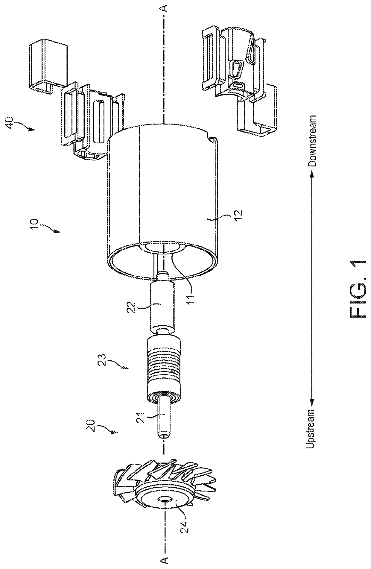
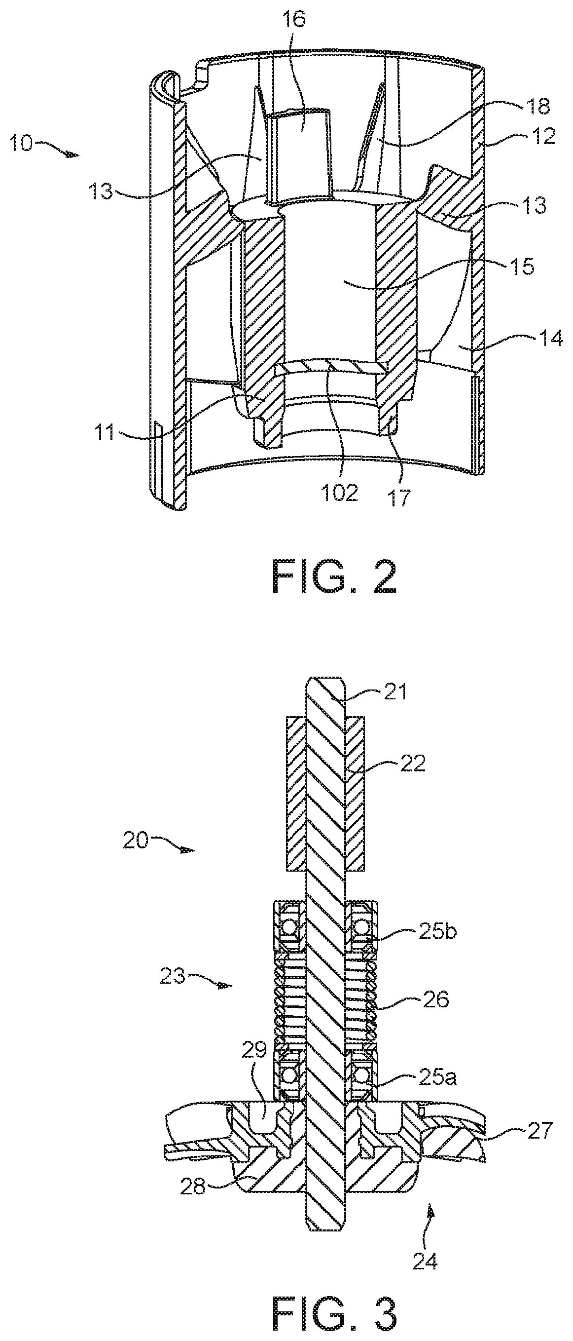
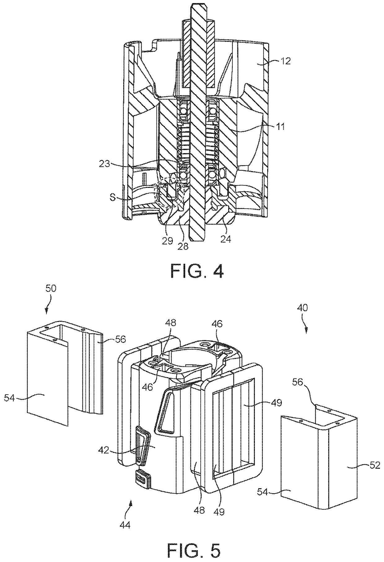
[0030]For the sake of clarity, the term “axial” is intended to mean in the direction of an axis running along a rotational axis of the motor as depicted by axis A-A in FIG. 1. In addition, the directional terms “upstream” and “downstream” referred to herein refer to the direction of airflow through the motor when in use and are further clarified by the double headed arrow in FIG. 1.

[0031]FIG. 1 is an exploded perspective view of an electric motor 1. The motor 1 comprises a frame 10, a rotor assembly 20 and a stator assembly 40. A cross-section through the frame 10 is shown in FIG. 2. The frame 10 comprises an inner wall 11 and an outer wall 12. The outer wall 12 surrounds the inner wall 11 such that an annular channel 14 is defined between them. A number of diffuser vanes 13 extend between the inner wall 11 and the outer wall 12 through the annular channel 14. The inner wall 11 is shorter in length than the outer wall 12, and the inner wall 11 is positioned such that the outer wall ...


PUM


Abstract

An electric motor having a frame, a rotor assembly, and a stator assembly. The rotor assembly has a magnet, a bearing assembly, an impeller, and a shaft. The bearing assembly has a first bearing, a second bearing, and a biasing element between the first and second bearings. The first bearing is mounted to the frame by an o-ring, and the second bearing is mounted to the frame by adhesive.

Description

REFERENCE TO RELATED APPLICATIONS[0001]This application is a national stage application under 35 USC 371 of International Application No. PCT / GB2019 / 050447, filed Feb. 19, 2019, which claims the priority of United Kingdom Application No. 1803348.0 filed Mar. 1, 2018, the entire contents of each of which are incorporated herein by reference.FIELD OF THE DISCLOSURE[0002]The present disclosure relates to an electric motor.BACKGROUND OF THE DISCLOSURE[0003]There is a general desire to improve electric machines, such as brushless electric motors, in a number of ways. In particular, improvements may be desired in terms of size, weight, manufacturing cost, efficiency, reliability and noise.[0004]It is becoming more and more common for electric machines such as brushless electric motors to be used a very high speeds, for example at 100 krpm or more. When operating at such high speeds, the motor may have undesirable acoustic characteristics. There is therefore a need to find improvements to ...

Claims


Application Information

Patent Timeline
Patent Type & Authority Applications(United States)
IPC IPC(8): H02K5/173H02K5/24H02K9/06
CPCH02K5/24H02K9/06H02K5/1732H02K7/083H02K5/163H02K5/1735H02K5/161
Inventor DYMOND, NIGEL YOUATTJI, LINGARCIA, KEVIN
Owner DYSON TECH LTD
Learn More