Overshoot amount detection method, overshoot amount detection system, robot system, and overshoot amount adjustment method

a technology of overshoot amount and detection method, which is applied in the direction of manipulators, gripping heads, program-controlled manipulators, etc., can solve the problems of drift and difficulty in accurate detection of overshoot amount of the arm

Active Publication Date: 2020-12-31
SEIKO EPSON CORP
View PDF0 Cites 0 Cited by
  • Summary
  • Abstract
  • Description
  • Claims
  • Application Information

AI Technical Summary

Benefits of technology

[0005]An overshoot amount detection method according to an aspect of the present disclosure includes generating a first signal by twice integration on a first detection signal output from an inertial sensor that detects inertia in a working unit of an arm to be displaced and removal of a low-frequency component contained in the first detection signal, generating a second signal for supplement of the low-frequency component of the first signal from a second detection signal output from an encoder that detects an amount of displacement of the arm, and detecting an overshoot amount of the arm based on the first signal and the second signal.

Problems solved by technology

When the acceleration signal output from the acceleration sensor is integrated twice, drift occurs due to noise, and it is necessary to remove a low-frequency component signal contained in the acceleration signal from the signal when the integration is performed by filtering processing or the like.
However, the low-frequency component is an important component indicating the movement of the arm, and there is a problem that, if the low-frequency component is removed, accurate detection of overshoot amount of the arm is difficult.

Method used


Image

  • Overshoot amount detection method, overshoot amount detection system, robot system, and overshoot amount adjustment method
  • Overshoot amount detection method, overshoot amount detection system, robot system, and overshoot amount adjustment method
  • Overshoot amount detection method, overshoot amount detection system, robot system, and overshoot amount adjustment method

Examples


Embodiment Construction

[0009]As below, an overshoot amount detection method, overshoot amount detection system, robot system, and overshoot amount adjustment method according to the present disclosure will be explained in detail based on an embodiment shown in the accompanying drawings.

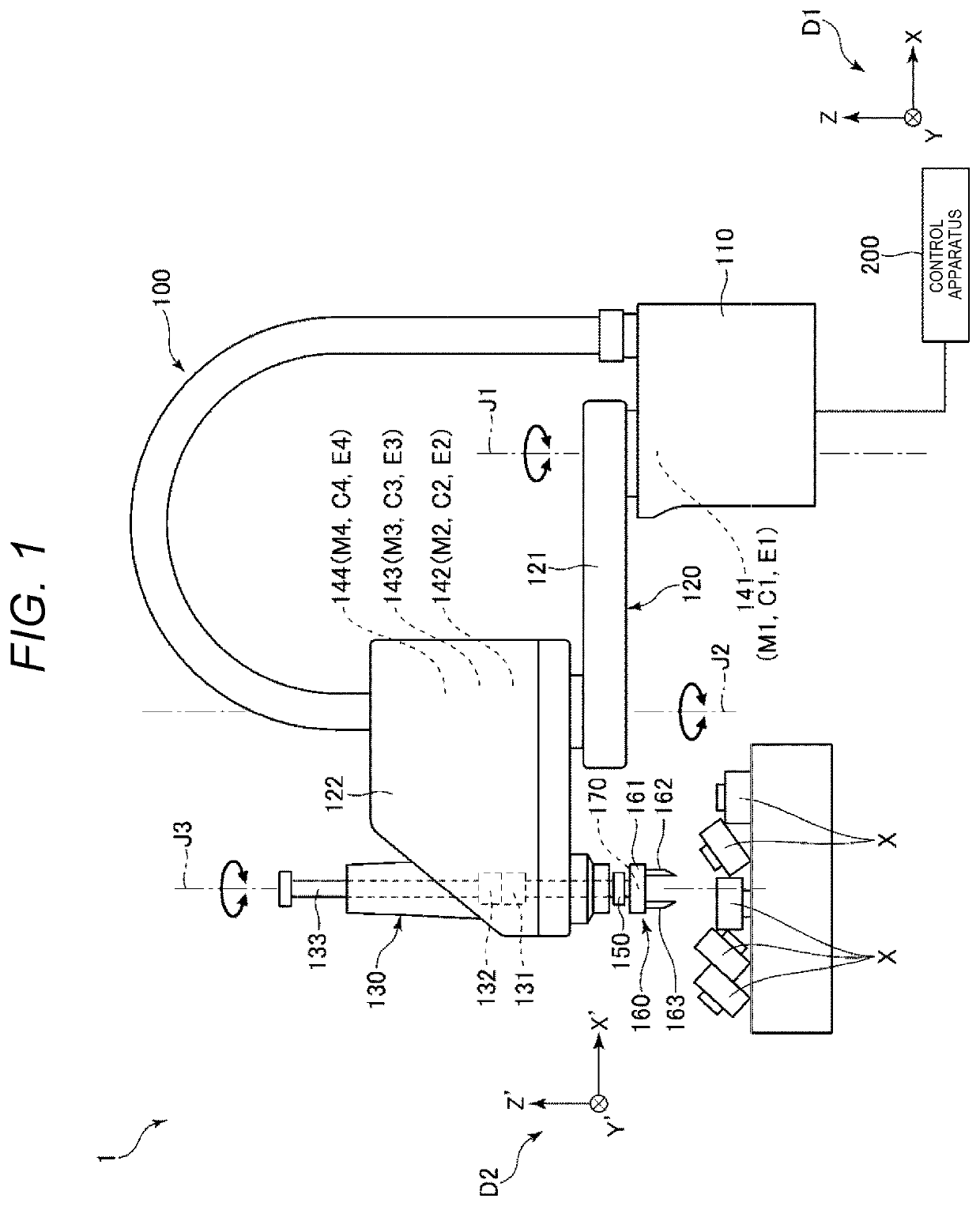
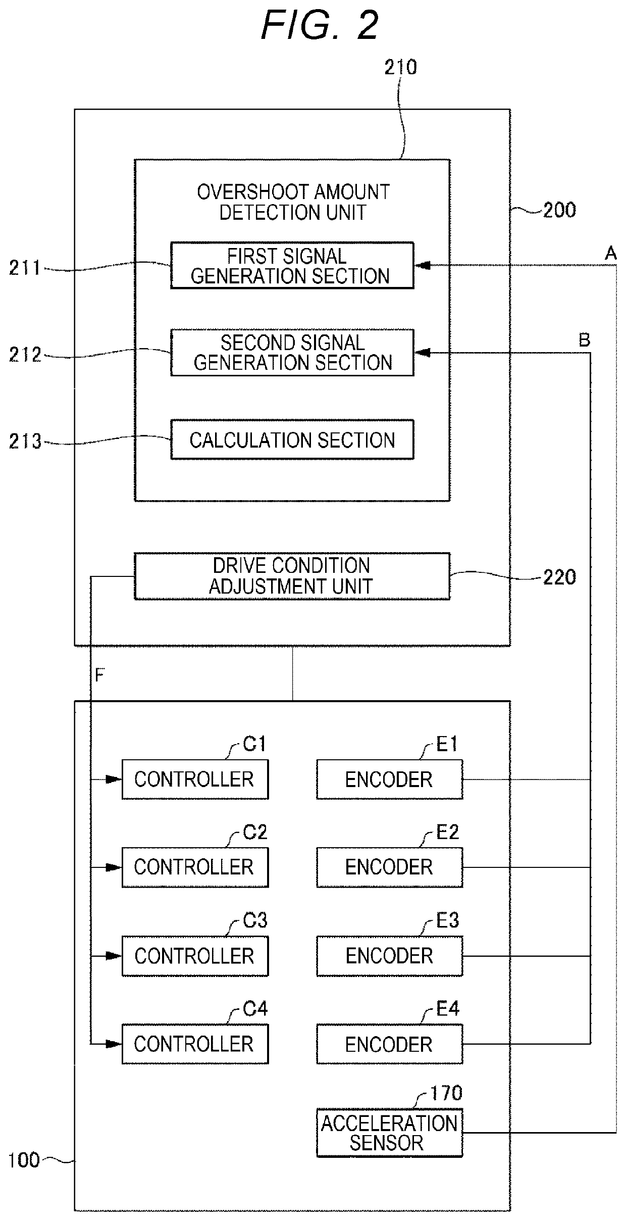
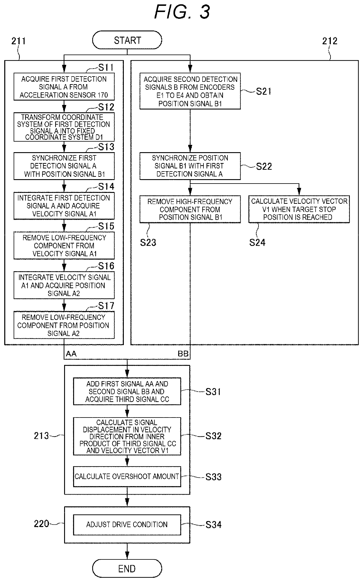
[0010]FIG. 1 shows the overall configuration of the robot system according to the preferred embodiment of the present disclosure. FIG. 2 is the block diagram showing the configuration of the control apparatus. FIG. 3 is the flowchart showing the detection method of the overshoot amount.

[0011]A robot system 1 shown in FIG. 1 has a robot main body 100 and a control apparatus 200 that controls driving of the robot main body 100.

[0012]First, the robot main body 100 is briefly explained. As shown in FIG. 1, the robot main body 100 is a horizontal articulated robot, i.e., scalar robot and used for respective work of e.g. holding, transport, assembly, inspection, etc. of works including electronic components. Note that the usage o...


PUM


Abstract

An overshoot amount detection method includes a first step of generating a first signal from a first detection signal output from an inertial sensor that detects inertia in a working unit of an arm to be displaced, a second step of generating a second signal using a second detection signal output from an encoder that detects an amount of displacement of the arm, and a third step of detecting an overshoot amount of the arm based on a third signal obtained by synthesis of the first signal and the second signal. The first step includes twice integration of the first detection signal and removing a low-frequency component contained in the first detection signal.

Description

[0001]The present application is based on, and claims priority from JP Application Serial Number 2019-119685, filed Jun. 27, 2019, the disclosure of which is hereby incorporated by reference herein in its entirety.BACKGROUND1. Technical Field[0002]The present disclosure relates to an overshoot amount detection method, overshoot amount detection system, robot system, and overshoot amount adjustment method.2. Related Art[0003]A robot control system disclosed in JP-A-2018-118353 has an acceleration sensor provided in an end effector and detects an overshoot amount from a set stop position of an arm based on a detection signal output from the acceleration sensor. Specifically, the robot control system detects a position of the arm by twice integration of an acceleration signal as the detection signal output from the acceleration sensor, and detects the maximum value of a difference between the detected position and the set stop position as the overshoot amount.[0004]When the acceleratio...

Claims


Application Information

Patent Timeline
Patent Type & Authority Applications(United States)
IPC IPC(8): B25J9/16B25J13/08
CPCB25J13/088B25J9/1638B25J13/087B25J15/06B25J18/00B25J19/0095B25J9/1694B25J9/1653
Inventor SEKI, RYUTAROMIZOBE, KIMITAKE
Owner SEIKO EPSON CORP
Why Eureka
Try Eureka