Method for measuring eddy current fields in a magnetic resonance device, magnetic resonance device, computer program and electronically readable data carrier

a magnetic resonance device and data carrier technology, applied in the direction of measurement devices, instruments, magnetic resonance, etc., can solve the problems of diffusion gradients, inadequate suppression of magnetic resonance signals, and insufficient suppression of signals, so as to achieve more time-consuming and labor-intensive effects

Active Publication Date: 2020-12-24
SIEMENS HEALTHCARE GMBH
View PDF0 Cites 0 Cited by
  • Summary
  • Abstract
  • Description
  • Claims
  • Application Information

AI Technical Summary

Benefits of technology

[0046]The implementation based on inheritance offers the advantage that, with little effort, it is possible to create different versions of the complete sequence based on different variants of the preparation sequence, for example for turbo spin echo sequences (TSE sequences), EPI diffusion sequences, etc. This makes it easy to implement complete sequences that measure the eddy current behavior for different clinical magnetic resonance sequences. As a result of the inheritance, the new, derived class now offers all (or the most important and expedient) functionalities of the original base class. This is advantageous, for example, to measure the effects of the eddy currents that occur during the playout of clinically or diagnostically relevant magnetic resonance sequences with different parameterizations, corresponding to different values of the protocol parameters. It is therefore advantageous if the underlying magnetic resonance sequence may be used directly as the basis, without the need firstly to retrospectively program the behavior of this sequence. A retrospective programming might be more time-consuming and labor-intensive, and there would be the risk of an incomplete match.
[0047]The variable may be generated successively for several different points in time and / or directions of pulse effect and / or parameterizations of the magnetic resonance sequence. In this way, it is therefore possible to perform analyses to identify the causes of image quality problems, for example. Equally, it is possible for the variable characterizing the eddy current field to be evaluated in order to parameterize at least one compensation measure for the eddy current field. A compensation measure may be the use of compensation gradient pulses, for example. However, the result of the measurement using the method also makes it possible to determine parameters of the magnetic resonance sequence in such a way that the eddy current effects, for example at certain points in time, are minimized.

Problems solved by technology

Magnetic fields induced by eddy currents, also referred to as eddy current fields, that may occur during a magnetic resonance sequence, represent a problem in the connection.
The disturbance may result for example in the magnetic resonance signal being inadequately suppressed by protons bound in fat, or in the signal being suppressed in an unwanted manner by protons bound in water.
Because the diffusion gradients usually include high amplitudes or large gradient moments, the diffusion gradients may also generate considerable eddy currents.
However, in commercially available magnetic resonance devices it is only possible to compensate eddy current fields that may be approximated by linear combinations, hence combinations of different gradients.
The calculations are however extremely time-consuming and labor-intensive as well as prone to error, and also require an exact characterization based on extensive calibration measurements of the respective magnetic resonance device in order to receive reliable results.

Method used


Image

  • Method for measuring eddy current fields in a magnetic resonance device, magnetic resonance device, computer program and electronically readable data carrier
  • Method for measuring eddy current fields in a magnetic resonance device, magnetic resonance device, computer program and electronically readable data carrier
  • Method for measuring eddy current fields in a magnetic resonance device, magnetic resonance device, computer program and electronically readable data carrier

Examples


Embodiment Construction

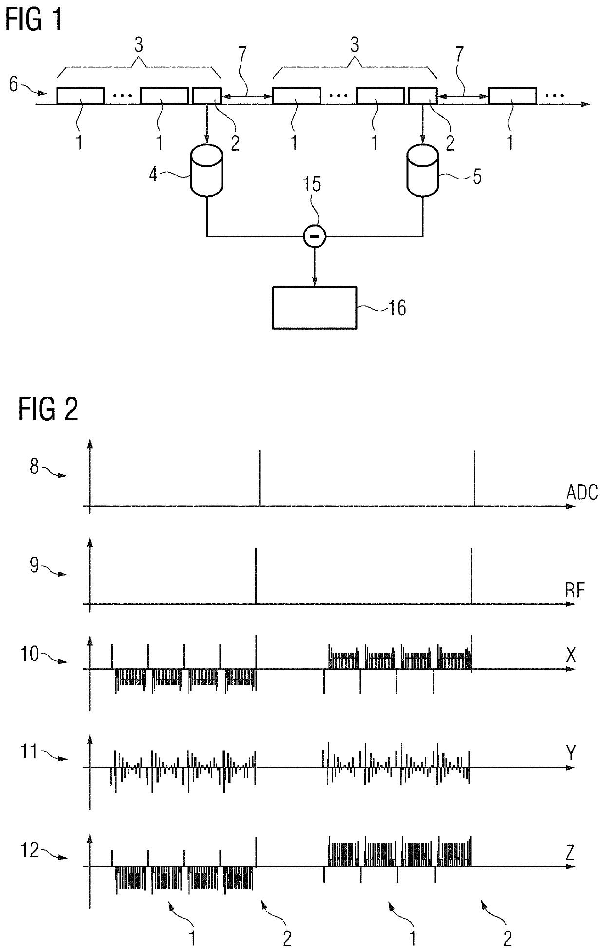
[0056]FIG. 1 depicts a functional sketch to explain a method for measuring eddy current fields occurring as a result of gradient pulses of a magnetic resonance sequence at a point in time during the magnetic resonance sequence in relation to at least one direction of pulse effect.

[0057]Parameters of the magnetic resonance sequence, the point in time and the at least one direction of pulse effect, for example as all directions of pulse effect of a Cartesian coordinate system, for example the X direction, the Y direction and the Z direction, for which gradient coils are also provided in the magnetic resonance device, are already predefined. The point in time is expediently to be selected as the end point of the magnetic resonance sequence or as a point in time during the execution of the magnetic resonance sequence at which the magnetic resonance sequence reacts sensitively to eddy current fields, that occur as field disturbances on account of eddy currents caused by gradient pulses o...


PUM


Abstract

Systems and methods for measuring eddy current fields occurring as a result of gradient pulses in a magnetic resonance sequence at a point in time during the magnetic resonance sequence in relation to at least one direction of pulse effect. At least the parts of the magnetic resonance sequence comprising the gradient pulses relating to the at least one direction of pulse effect are performed as a preparation sequence up until the point in time followed directly by a measurement sequence in which first measurement data is recorded. The preparation sequence is played out again with the same, directly consecutive measurement sequence without the gradient pulses relating to the at least one direction of pulse effect or with gradient pulses having an inverted sign relating to the at least one direction of pulse effect. Second measurement data is recorded. Using a joint evaluation of the first and second measurement data at least one variable characterizing the eddy current field generated by the eddy currents of the gradient pulses in the at least one direction of pulse effect is determined.

Description

CROSS REFERENCE TO RELATED APPLICATIONS[0001]This application claims the benefit of DE 102019209079.6 filed on Jun. 24, 2019, which is hereby incorporated by reference in its entiretyFIELD[0002]Embodiments relate to a system and method for measuring eddy current fields occurring as a result of gradient pulses of a magnetic resonance sequence at a point in time during the magnetic resonance sequence in relation to at least one direction of pulse effect.BACKGROUND[0003]Magnetic resonance imaging is an established modality, for example in medical engineering. Nuclear spins aligned in a main magnetic field, for example in a patient, are excited by radio frequency pulses and the decay of the excitation is measured. Today's research with regard to magnetic resonance devices is aimed at improving image quality.[0004]Magnetic fields induced by eddy currents, also referred to as eddy current fields, that may occur during a magnetic resonance sequence, represent a problem in the connection. S...

Claims


Application Information

Patent Timeline
Patent Type & Authority Applications(United States)
IPC IPC(8): G01R33/565G01R33/54
CPCG01R33/543G01R33/56518G01R33/56572G01R33/24
Inventor KÖHLER, MICHAEL
Owner SIEMENS HEALTHCARE GMBH
Why Eureka
Try Eureka