Turbine Engine Outer Shroud

Active Publication Date: 2020-12-17
SAFRAN AERO BOOSTERS SA
View PDF0 Cites 2 Cited by
  • Summary
  • Abstract
  • Description
  • Claims
  • Application Information

AI Technical Summary

Benefits of technology

The invention aims to solve problems in the prior art by providing a simpler and more compact design that allows for easier mounting of vanes with variable orientation and the mechanism for actuating their orientation. The invention also aims to provide a light solution. The cylindrical surface surrounds the flanges, making the whole assembly more compact, and the positioning of the cylindrical surface above the flanges allows for good rigidity of the seat of the actuating device.

Problems solved by technology

Such a shroud is cumbersome.
In a compressor with a shorter shroud or fewer compression stages, such a mechanism is unnecessarily cumbersome.

Method used


Image

  • Turbine Engine Outer Shroud
  • Turbine Engine Outer Shroud
  • Turbine Engine Outer Shroud

Examples


Embodiment Construction

[0042]In the following description, the terms “internal” and “external” refer to a positioning relative to the axis of rotation of an axial turbomachine. The axial direction corresponds to the direction along the axis of rotation of the turbomachine. The radial direction is perpendicular to the axis of rotation.

[0043]Upstream and downstream are in reference to the main flow direction of the flow in the turbomachine.

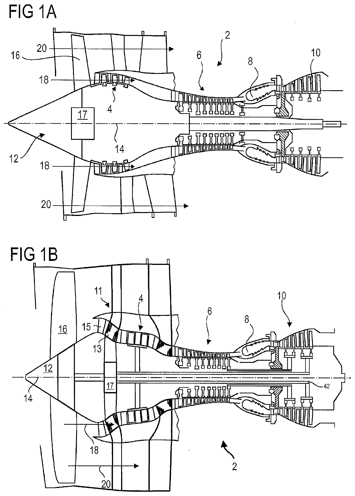
[0044]FIG. 1A shows a simplified axial turbomachine. This is here a two-stream turbojet engine. The turbojet engine 2 comprises a first stage of compression, called a low-pressure compressor 4, a second stage of compression, called a high-pressure compressor 6, a combustion chamber 8 and one or more stages of turbines 10. In operation, the mechanical power from the turbine 10 transmitted via the central shaft to the rotor 12 sets in motion the two compressors 4 and 6. The latter comprise several rows of rotor vanes associated with rows of stator vanes. The rotation of the...


PUM


Abstract

The invention relates to a turbine engine (2) compressor shroud, comprising: first and second sections (130, 230) and respective flanges (131, 231), the flanges (131, 231) making it possible to hold the two sections (130, 230) together, the first section (130) comprising a cylindrical surface (137) forming a seat for an actuating device (136, 140, 166, 168, 170) for orienting stator blades (126), characterised in that the first shroud (130) comprises a tubular wall (132) axially overlapping both flanges (131, 231) and said cylindrical surface (137) is an outer surface of the tubular wall (132). The invention also relates to an assembly with the shroud (130,230), the blade (126) and means (140) for actuating the orientation of the blade (126), the shroud being produced using the kit described above. The invention finally relates to a method for assembling a compressor with such an assembly.

Description

TECHNICAL FIELD[0001]The invention relates to the field of axial turbomachinery and more particularly aircraft turbojets. More specifically, the invention relates to the design of an outer shroud of a compressor provided with stator vanes with variable orientation. The invention also relates to an assembly kit and a turbomachine provided with such a shroud, as well as an assembly method.BACKGROUND ART[0002]The document US 2016 / 0160675 describes an axial turbomachine with a particular arrangement of the trunnions of stator vanes with variable orientation in an external compressor shroud. The vane orientation actuation system is positioned downstream of each vane. A connecting rod, denoted 80, makes it possible to adjust the pivoting of the vanes. This connecting rod can be manipulated by a synchronization ring, so that all the vanes of a given stage are oriented synchronously. The synchronization ring is also called a handling ring, an actuation ring or a control ring.[0003]Such a ri...

Claims


Application Information

Patent Timeline
IPC IPC(8): F01D17/16F04D29/56F04D29/64
CPCF04D29/563F05D2240/128F04D29/644F05D2220/32F01D17/162F05D2220/323F05D2230/60
Inventor VYVEY, MORGAN
Owner SAFRAN AERO BOOSTERS SA
Why Eureka
Try Eureka