
System and method for siting of energy storage systems in an elegrical grid, incuding optimizing locations of energy storage systems based on thechnical parameters of an energy storage system or other parameters

a technology of energy storage system and elegrical grid, which is applied in the direction of adaptive control, process and machine control, instruments, etc., can solve the problems of limiting the performance of the facility, accelerating the diminishment of the overall calendar life of the facility, and significant information gaps, so as to maximize the potential for energy-intensive arbitrage based operation, maximize the potential for energy-intensive arbitrage periods, and flexible and highly automated

Active Publication Date: 2020-12-10
JUPITER POWER LLC
View PDF0 Cites 1 Cited by
  • Summary
  • Abstract
  • Description
  • Claims
  • Application Information

AI Technical Summary

Benefits of technology

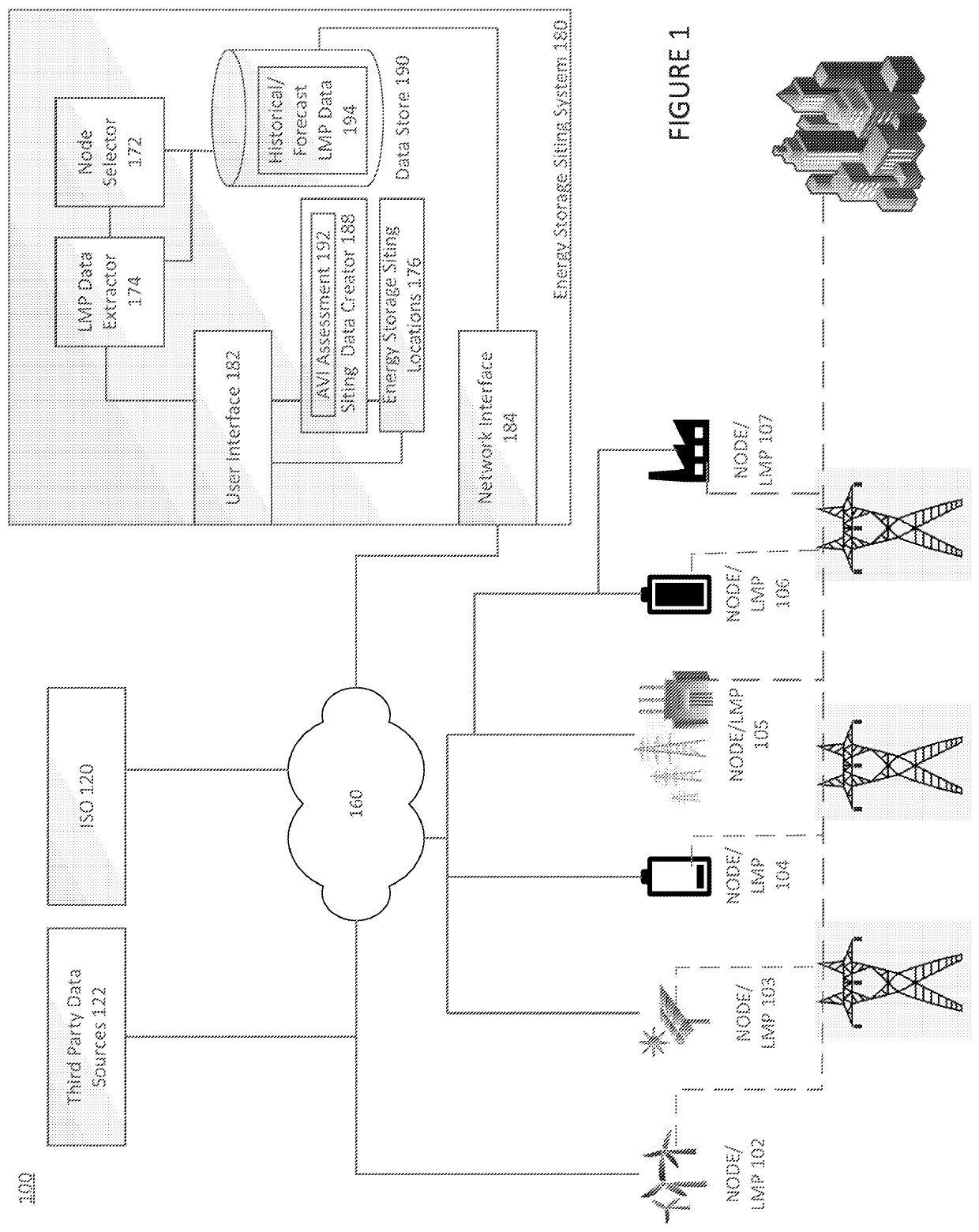
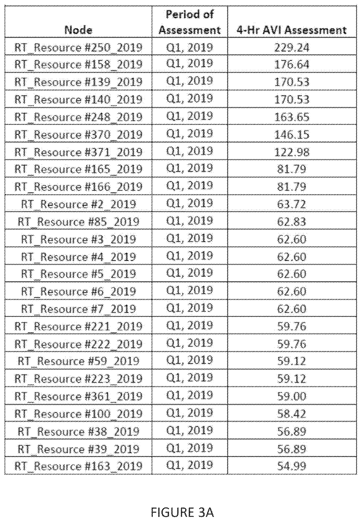
The patent is about a system that helps to maximize the energy storage of a battery in a power grid by finding the best place for the battery based on factors like location, price signals, and storage capacity. This system uses an Arbitrage Value Index (AVI) to evaluate the energy arbitrage potential at each distinct node in the grid and suggest the best locations for energy storage. The system is flexible and can evaluate the AVI for different battery durations, amounts of storage, and cycle rates. This system provides an efficient and automated way to evaluate thousands of nodes in a power grid and design energy storage facilities based on the optimal site locations and technical parameters.

Problems solved by technology

This situation creates a significant information gap for energy storage resources (e.g., batteries or the like) operating in an electrical grid governed by such an electricity market, as these systems can only operate for a limited period of time in a given deployment.
Absent a methodology to analyze the combined implications of energy storage location and technical parameters such as energy storage duration within the uncertain operating environment of the electric grid, a battery storage facility may be sited at a location where the facility will be inefficiently used or inadequately sized, thereby limiting the performance of the facility and potentially accelerating diminishment in its overall calendar life.
Prior attempts to determine siting of energy storage facilities on the grid, have suffered from a number of issues.
Moreover, most of these solutions may only be utilized with a limited number of nodes, rendering them essentially useless for applicability to a modern electricity grid which may comprise many thousands of such nodes (e.g., 10,000 nodes or more).

Method used


Image

  • System and method for siting of energy storage systems in an elegrical grid, incuding optimizing locations of energy storage systems based on thechnical parameters of an energy storage system or other parameters
  • System and method for siting of energy storage systems in an elegrical grid, incuding optimizing locations of energy storage systems based on thechnical parameters of an energy storage system or other parameters
  • System and method for siting of energy storage systems in an elegrical grid, incuding optimizing locations of energy storage systems based on thechnical parameters of an energy storage system or other parameters

Examples


Embodiment Construction

[0024]In the following description of the present invention there are multiple details established to provide a thorough understanding of the invention and the preferred implementations of the invention. It should be clear that the description is not intended to limit the invention to these specific embodiments and those variations, changes, substitutions, or equivalent components will be apparent to those skilled in the art and should not be considered significant differences from the intended scope of the invention.

[0025]The invention and the various features and advantageous details thereof are explained more fully with reference to the nonlimiting embodiments that are illustrated in the accompanying drawings and detailed in the following description. Descriptions of well-known starting materials, processing techniques, components and equipment are omitted so as not to unnecessarily obscure the invention in detail. It should be understood, however, that the detailed description a...


PUM


Abstract

Systems and methods for identifying optimal siting locations for an energy storage system. Siting locations are identified based on a value index derived from pricing data associated with a plurality of nodes on an electrical grid. An index is derived for each selected node of the plurality of nodes to produce a siting recommendation.

Description

CITATION TO PRIOR APPLICATIONS[0001]The present application is a continuation of and claims priority to U.S. Provisional Application No. 62 / 848,376, titled “SYSTEM AND METHOD FOR SITING OF ENERGY STORAGE SYSTEMS IN AN ELECTRICAL GRID, INCLUDING OPTIMIZING LOCATIONS OF ENERGY STORAGE SYSTEMS BASED ON TECHNICAL PARAMETERS OF AN ENERGY STORAGE SYSTEM OR OTHER PARAMETERS” and filed on or about May 15, 2020.BACKGROUND OF THE INVENTION[0002]Electrical grids are collections of transmission and distribution power lines interconnecting resources which generate power with loads which consume power. The operation of many electrical grids in the United States is governed by a set of Independent System Operators (ISOs) (e.g., ERCOT, PJM, MISO, NYISO, etc.) or Regional Transmission Organizations (RTOs) that plan or operate a respective associated grid. These ISOs and RTOs (collectively “ISO” herein) are thus responsible for reliably operating and planning the associated electricity grids and the ...

Claims


Application Information

Patent Timeline
Patent Type & Authority Applications(United States)
IPC IPC(8): G05F1/66H02J3/00G06Q10/06G05B13/04
CPCG06Q10/063H02J3/004G05B13/048G05F1/66H02J3/28H02J3/381G06Q50/06Y04S10/50Y02E40/70
Inventor SAHNI, MANDHIRFOGARTY, JR., AUDREYBOWMAN, ANDREW
Owner JUPITER POWER LLC
Learn More