


Quick Research
Generate reliable direction feasibility study reports for your R&D in just a few steps.

Technical Q&A
Discover and master advanced knowledge NOW. Basics, ideas, possibilities, all at once.

Find Solutions
As an expert in R&D theories, this can generate solutions to your technical problems instantly.

Evaluate Feasibility
Analyze your overall solution with one click, know your potential R&D risks in advance.

Monitor Landscape
Get weekly tech updates, stay abreast of the latest tech innovations and key insights.
Initial positioning system and method for liquid measuring and removing
a liquid measurement and positioning system technology, applied in the field of initial positioning system for liquid measurement and taking, can solve the problems of affecting measurement accuracy, waste of liquids and polluting, and traditional measuring tools used, and achieves convenient positioning and measurement, high operation sensitivity, and simple operation.
- Summary
- Abstract
- Description
- Claims
- Application Information
AI Technical Summary
Benefits of technology
Problems solved by technology
Method used
Image

Examples
embodiment 1
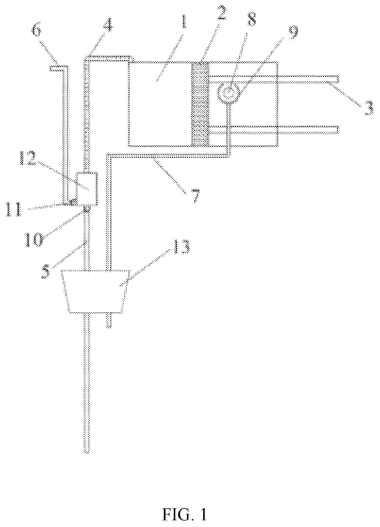
[0029]Embodiment 1 provides a measuring tool including an initial positioning system for liquid measuring and taking, as shown in FIG. 1. The initial positioning system of the measuring tool includes a variable-pressure chamber 1, a piston 2, an operating rod 3, a measuring channel 4 and a pressure relief port 8. The piston 2 is located on a level side of the variable-pressure chamber 1. The measuring channel 4 communicates with an upper part of the variable-pressure chamber 1. The pressure relief port 8 is located at a middle or upper part of a level of the variable-pressure chamber 1 and passes through a wall of the variable-pressure chamber 1. The piston 2 can move across the pressure relief port 8 to the right of the pressure relief port 8 when reciprocating. When the piston 2 is located at the pressure relief port 8 and the inside and outside of the variable-pressure chamber 1 are communicated, a maximum volume of the liquid in the variable-pressure chamber 1 is two thirds tota...
embodiment 2
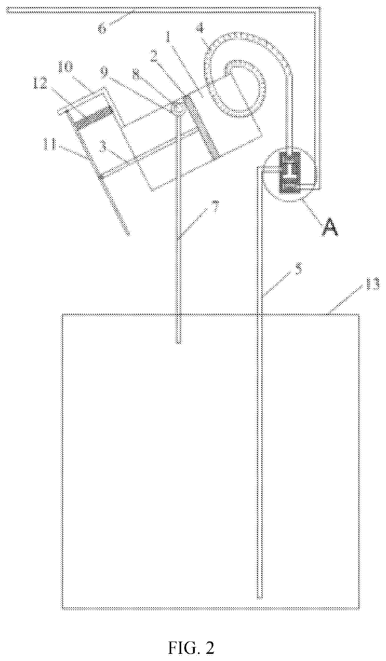
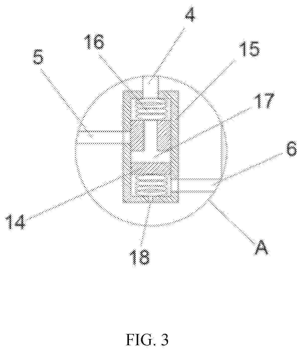
[0036]Embodiment 2 provides a container for liquid measuring and taking, as shown in FIG. 2. FIG. 3 is a detail drawing of A in the container for liquid measuring and taking in Embodiment 2.
[0037]The container for liquid measuring and taking includes an initial positioning system composed of a variable-pressure chamber 1, a piston 2, a connecting rod 3, a measuring channel 4 and a pressure relief port 8. The container further includes a bowl 9 covering the outside of the pressure relief port 8, a return channel 7, a liquid taking channel 5, an outflow channel 6, a steering valve, a container body 13, and facilities for easy taking, including a bracket 10 fixed on an outer wall of the variable-pressure chamber 1, an operating rod 11 in movable connection with the bracket 10 and the connecting rod 3, and a spring 12 located between the bracket 10 and the operating rod 11.
[0038]The piston 2 is located on an oblique lower side of the variable-pressure chamber 1. The measuring channel 4 ...
embodiment 3
[0048]Embodiment 3 provides a container for liquid measuring and taking, as shown in FIG. 4. The container for liquid measuring and taking includes an initial positioning system composed of a variable-pressure chamber 1, a piston 2, a connecting rod 3, a measuring channel 4 and a pressure relief port 8. The pressure relief port is provided with a valve opened under a certain pressure. The container further includes a return channel 7, a liquid taking channel 5 and an internal check valve 10 thereof, an outflow channel 6 and an internal check valve 11 thereof, a container body 13, and an electric device 12 connected to the connecting rod 3. The return channel is connected outside the pressure relief port 8, and an upper part of the return channel 7 is provided with an opening 9.
[0049]The piston 2 is located at a lower side of the variable-pressure chamber 1. The measuring channel 4 communicates with an upper right part of the variable-pressure chamber 1. The pressure relief port 8 is...
PUM
 Abstract
Description
Claims
Application Information
 - R&D Engineer
- R&D Manager
- IP Professional
- Industry Leading Data Capabilities
- Powerful AI technology
- Patent DNA Extraction
Browse by: Latest US Patents, China's latest patents, Technical Efficacy Thesaurus, Application Domain, Technology Topic, Popular Technical Reports.
© 2024 PatSnap. All rights reserved.Legal|Privacy policy|Modern Slavery Act Transparency Statement|Sitemap|About US| Contact US: help@patsnap.com