
Panel mount connector

a panel mount and connector technology, applied in the field of connectors, can solve the problems of difficult access to the inside of the panel, difficult routine checks, maintenance or changes, and the cable cannot be removed, so as to improve the resistance to mating forces and blind mate impact forces, the effect of easy maintenance and inspection of the system

Active Publication Date: 2020-10-01
MOLEX INC
View PDF0 Cites 0 Cited by
  • Summary
  • Abstract
  • Description
  • Claims
  • Application Information

AI Technical Summary

Benefits of technology

This patent describes a connector that can be easily mounted onto a panel and support a terminal module. The connector has a lip or other features that securely attach the housing to the panel and a secondary piece that takes the forces from the terminal module and transfers them to the housing. This design makes maintenance easier and increases resistance to mating forces and blind mate impact forces, ensuring reliable and safe connection.

Problems solved by technology

As can be appreciated, these existing designs constrain the cable with the terminal module and do not allow the cable to be removed without removing and disassembling the entire panel mount connector.
Routine checks, maintenance or changes become difficult with existing solutions as it can be difficult to access the inside of the panel when the panel mount connector is part of a much larger system where space or access to the cable side 6 of the panel 5 is limited.

Method used


Image

  • Panel mount connector
  • Panel mount connector
  • Panel mount connector

Examples


Embodiment Construction

[0031]The detailed description that follows describes exemplary embodiments and is not intended to be limited to the expressly disclosed combination(s). Therefore, unless otherwise noted, features disclosed herein may be combined together to form additional combinations that were not otherwise shown for purposes of brevity.

[0032]Looking at FIGS. 5-10, features of a first type of embodiment of a panel mount connector are disclosed. A panel mount connector 100 includes housing 120 that defines one or more channels 127 and is configured to mount to the panel 5. Like with some panel mount connectors, the housing 120 includes an outer surface 121a that is sized to fit inside a panel aperture 8 with some amount of clearance so that the housing can move somewhat within the panel aperture 8. The channel 127 is configured to receive a terminal module 140 therein and will be sized appropriately. In operation, the housing 120 is inserted into the panel aperture 8 in the panel 5 from a terminal...


PUM


Abstract

A panel mount connector includes a housing that mounts to a panel from a terminal side of the panel and a terminal module that is configured to be supported by and inserted in a channel in the housing from a cable side of the panel. A secondary piece can be used to secure the terminal module to the housing and provide sufficient structure robustness while allowing for ease of assembly and disassembly.

Description

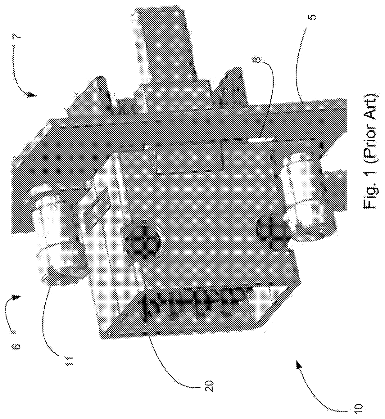
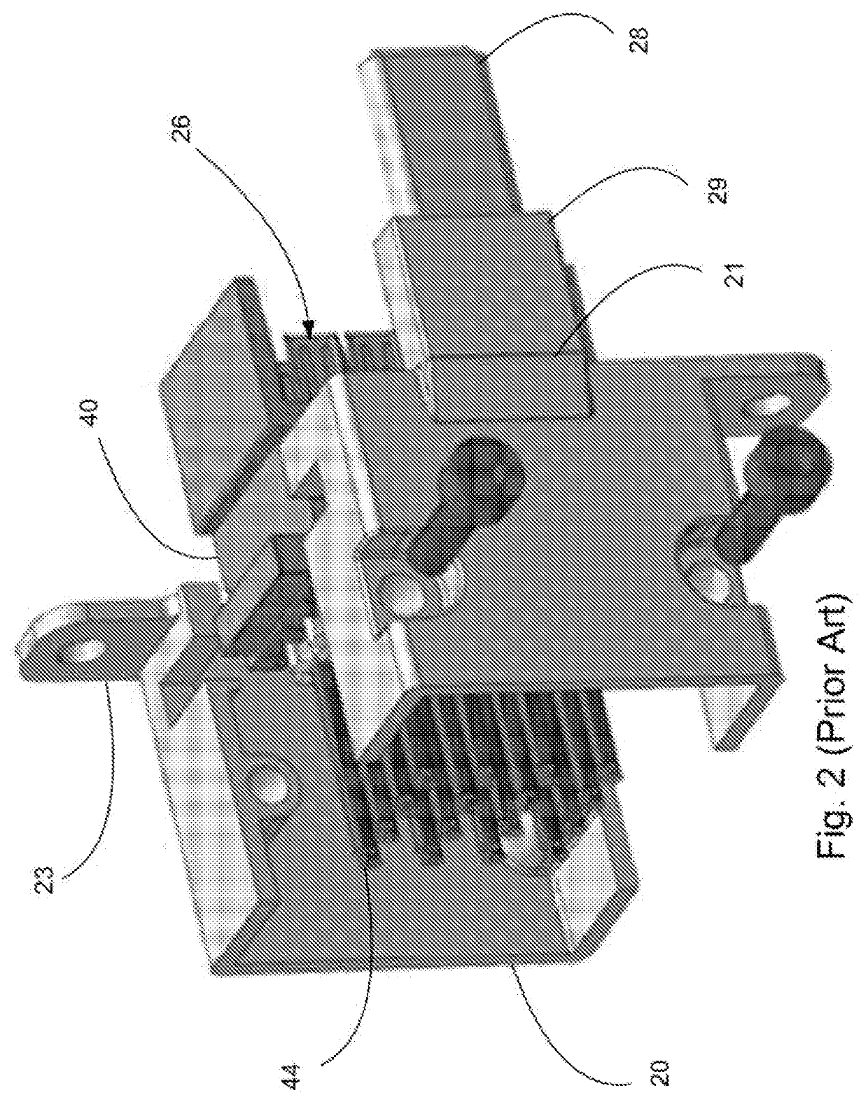
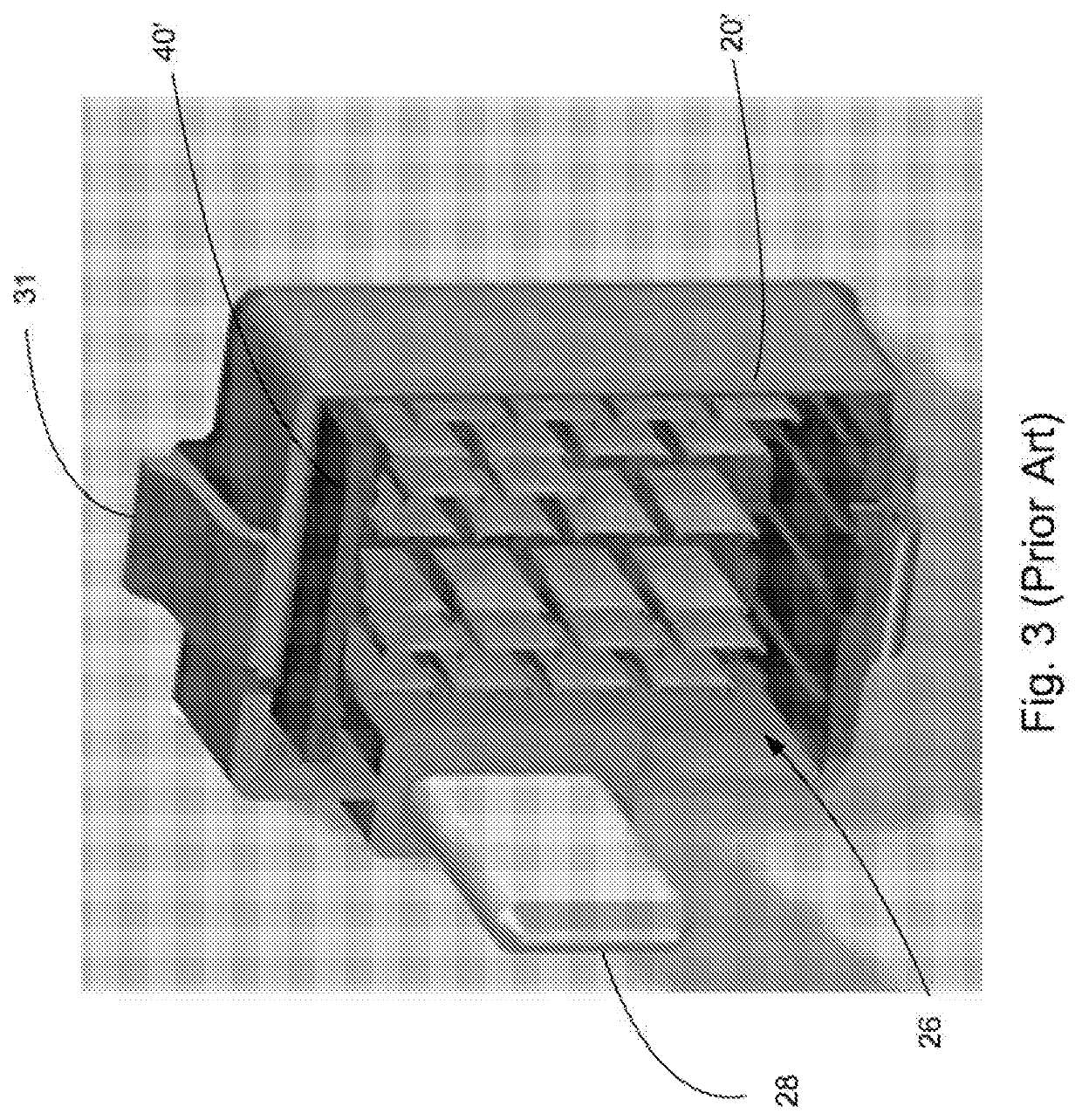
RELATED APPLICATIONS[0001]This application claims priority to U.S. Provisional Application No. 62 / 316,220, filed Mar. 31, 2016, which is incorporated herein by reference in its entirety.TECHNICAL FIELD[0002]This disclosure relates to the field of connectors, more specifically to connectors suitable for use in panel mount applications that can also support high data rates.DESCRIPTION OF RELATED ART[0003]Panel mount connectors are known. As can be appreciated from FIGS. 1-4, existing panel mount connectors, such as panel mount connector 10, have several issues if they are being used to support higher data rates. In a typical application, a panel mount connector assembly 10 includes a housing 20 that has a two-piece construction that partially envelops and supports a terminal module 40. The terminal module 40 includes a terminal array 26 that is connected to a plurality of cables 44 and supports the terminal array 26 and the cables 44 in the desired position within the housing 20. Once...

Claims


Application Information

Patent Timeline
Patent Type & Authority Applications(United States)
IPC IPC(8): H01R13/639H01R13/74
CPCH01R13/743H01R13/6395H01R13/639H01R13/74H01R13/4361H01R13/506
Inventor LAWRENCE, TOMMYRESENDEZ, JAVIERARAI, TAKAYUKI
Owner MOLEX INC
Learn More