
Eddy current sensor assembly

Active Publication Date: 2020-09-17
DANA AUTOMOTIVE SYST GRP LLC
View PDF0 Cites 3 Cited by
  • Summary
  • Abstract
  • Description
  • Claims
  • Application Information

AI Technical Summary

Benefits of technology

The patent describes a way to prevent a vehicle from skimming over uneven surfaces when its wheels are not in perfect contact with the ground. This is accomplished by using a locking differential that forces the wheels to rotate at the same speed, regardless of traction. To ensure the locking gear is securely locked, a sensor is used to monitor its status. This sensor uses eddy currents to create a magnetic field and measure its output, which is proportional to the distance between the sensor and the target material. This non-contact sensor is cost-effective and easy to use.

Problems solved by technology

During instances when one wheel is unintentionally stationary and all of the power is transferred to the remaining movable wheel, wheel slip may occur and may cause uncontrolled movement of the vehicle.
However, the locking gear may not immediately engage with the differential apparatus, leading to uncertainty regarding the locked state of the differential apparatus.

Method used


Image

  • Eddy current sensor assembly
  • Eddy current sensor assembly
  • Eddy current sensor assembly

Examples


Embodiment Construction

[0024]It is to be understood that the invention may assume various alternative orientations and step sequences, except where expressly specified to the contrary. It is also to be understood that the specific assemblies and systems illustrated in the attached drawings, and described in the following specification are simply exemplary embodiments of the inventive concepts defined herein. Hence, specific dimensions, directions or other physical characteristics relating to the embodiments disclosed are not to be considered as limiting, unless expressly stated otherwise. Also, although they may not be, like elements in various embodiments described herein may be commonly referred to with like reference numerals within this section of the application.

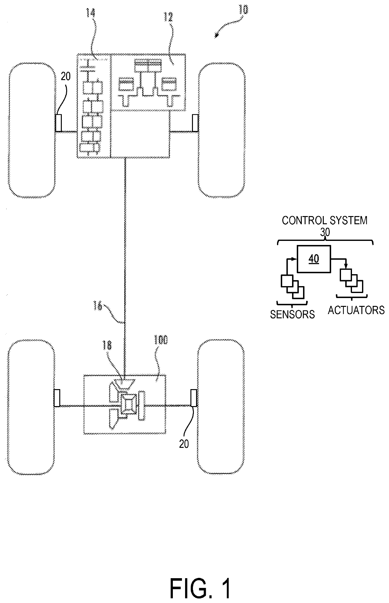
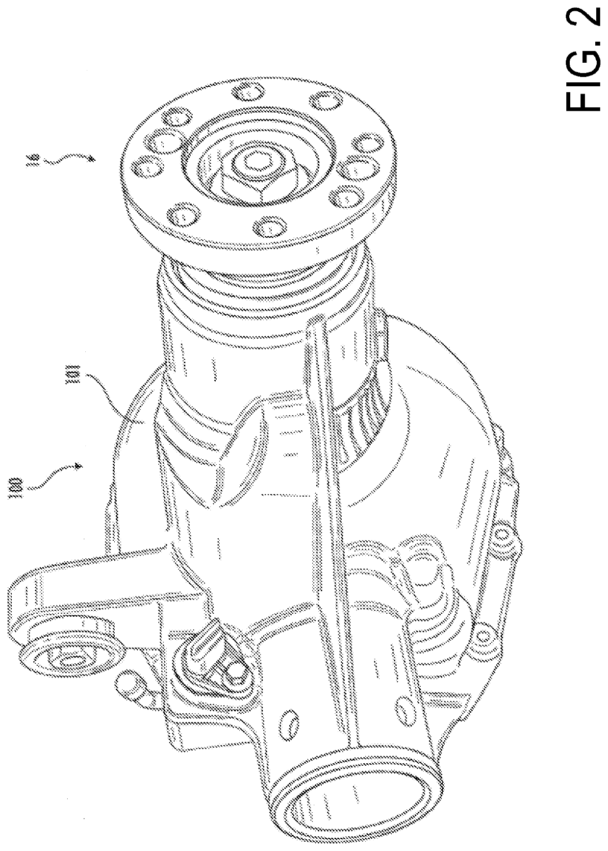
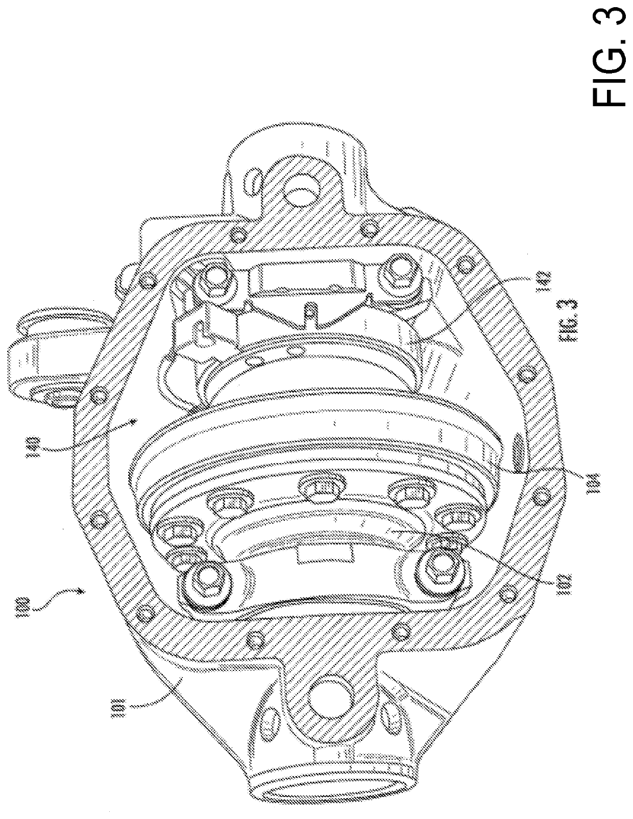
[0025]A differential apparatus may be implemented in an axle assembly of a vehicle to control an amount of torque delivered to wheels of the vehicle. An example of a vehicle is shown in FIG. 1 and an example of an axle assembly which may be c...


PUM


Abstract

Methods and systems are provided for a sensor assembly for a differential apparatus. In one example, the sensor assembly includes a microcontroller and an eddy current sensor communicatively coupled to the microcontroller and configured to detect a distance between an axially slidable and an axially stationary component of a differential apparatus.

Description

CROSS-REFERENCE TO RELATED APPLICATIONS[0001]The present application claims priority to U.S. Provisional Application No. 62 / 818,522, entitled “Eddy Current Sensor Assembly”, and filed on Mar. 14, 2019. The entire contents of the above-listed application are hereby incorporated by reference for all purposes.TECHNICAL FIELD[0002]The present disclosure relates to an eddy current sensor assembly, and more particularly to an eddy current sensor assembly for an electrical locking differential.BACKGROUND AND SUMMARY[0003]Electrical control of coupling large rotating mechanical components requires actuators to move the mechanical components over relatively long distances. For example, axle assemblies in vehicle drivetrains may utilize a differential apparatus to transmit torque from a power to vehicle wheels. The differential apparatus may enable an outer drive wheel to rotate at a greater velocity than an inner drive wheel when operating the vehicle through a turn, thereby dividing power b...

Claims


Application Information

Patent Timeline
IPC IPC(8): G01D5/20F16H48/24F16H48/34
CPCF16H48/34G01D5/2013F16H48/24F16H48/08G01B7/14G01D5/202F16H2048/346F16H2048/204F16H48/20F16D27/118F16D27/09
Inventor MCGRANER, TERRY W.PAIELLI, PERRY M.
Owner DANA AUTOMOTIVE SYST GRP LLC
Learn More