
Auxiliary electric source device and steering device

a technology of auxiliary electric sources and steering devices, which is applied in the direction of electrical steering, emergency power supply arrangements, transportation and packaging, etc., can solve the problems of increasing the performance of electric sources and not being able to achieve the maximum effect of fulfilling the desired function, and reducing the increase of electric sources performance. , to achieve the effect of restrainting the increase of electric sources

Inactive Publication Date: 2020-09-10
JTEKT CORP
View PDF0 Cites 0 Cited by
  • Summary
  • Abstract
  • Description
  • Claims
  • Application Information

AI Technical Summary

Benefits of technology

The disclosure describes an auxiliary electric source device and a steering device that can restrain the performance of the auxiliary electric source. This is helpful in situations where the main electric source fails. The auxiliary electric source device can provide enough electricity to maintain the minimum function of the steering device, even if its performance is not as good as the main source. This helps to avoid the need for an auxiliary electric source with the same performance as the main source, which can result in increased costs. The steering device can also maintain its function even if noise is generated during the electric feed. Overall, this solution helps to control the performance of the auxiliary electric source and reduces the need for expensive equipment.

Problems solved by technology

However, for the auxiliary electric source, it is also demanded to restrain increase in electric source performance.
That is, when the auxiliary electric source backs up the electric feed from the main electric source in the case where the main electric source has broken down, it is possible to fulfill at least the desired minimal function with the electric feed from the auxiliary electric source, although it is not possible to maximally fulfill the desired function.

Method used


Image

  • Auxiliary electric source device and steering device
  • Auxiliary electric source device and steering device
  • Auxiliary electric source device and steering device

Examples


Embodiment Construction

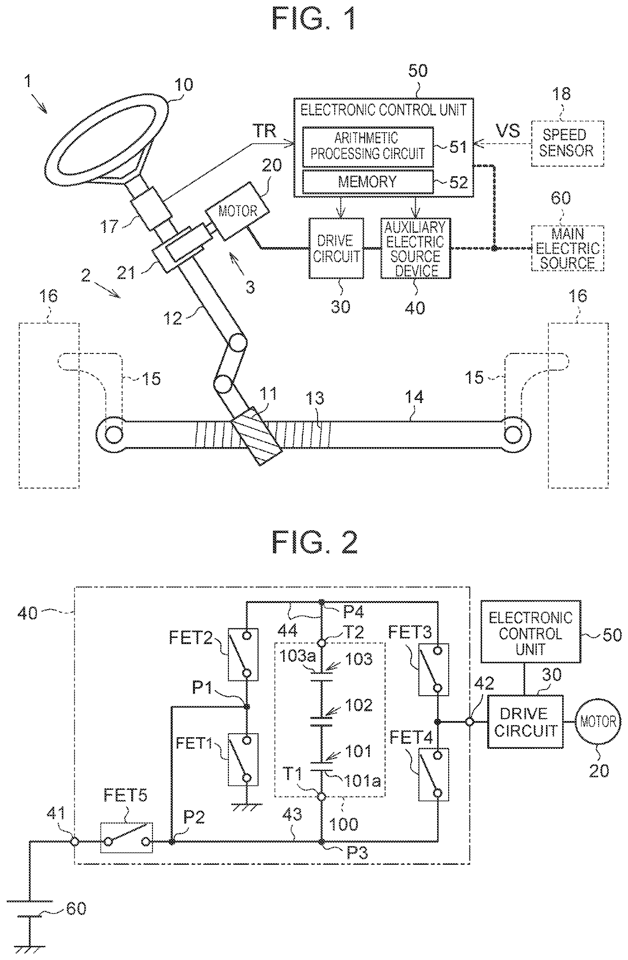
[0021]An embodiment in which an auxiliary electric source device is applied to an electric power steering device (referred to as an “EPS” hereinafter) will be described. As shown in FIG. 1, an EPS 1 in the embodiment includes a steering mechanism 2 that steers steered wheels 16 based on an operation of a steering wheel 10 by a driver, and an assist mechanism 3 that includes a motor 20 for assisting the steering operation by the driver. The EPS 1 has a function to assist the steering operation by the driver, by giving the motor torque of the motor 20 to the steering mechanism 2 as steering assist power.

[0022]The steering mechanism 2 includes a steering shaft 12 having one end at which the steering wheel 10 is fixed and the other end at which a pinion gear 11 is formed, and a rack shaft 14 on which a rack gear 13 that engages with the pinion gear 11 is formed. The pinion gear 11 and the rack gear 13 constitute a rack-and-pinion mechanism. A rotation motion of the steering shaft 12 is ...


PUM


Abstract

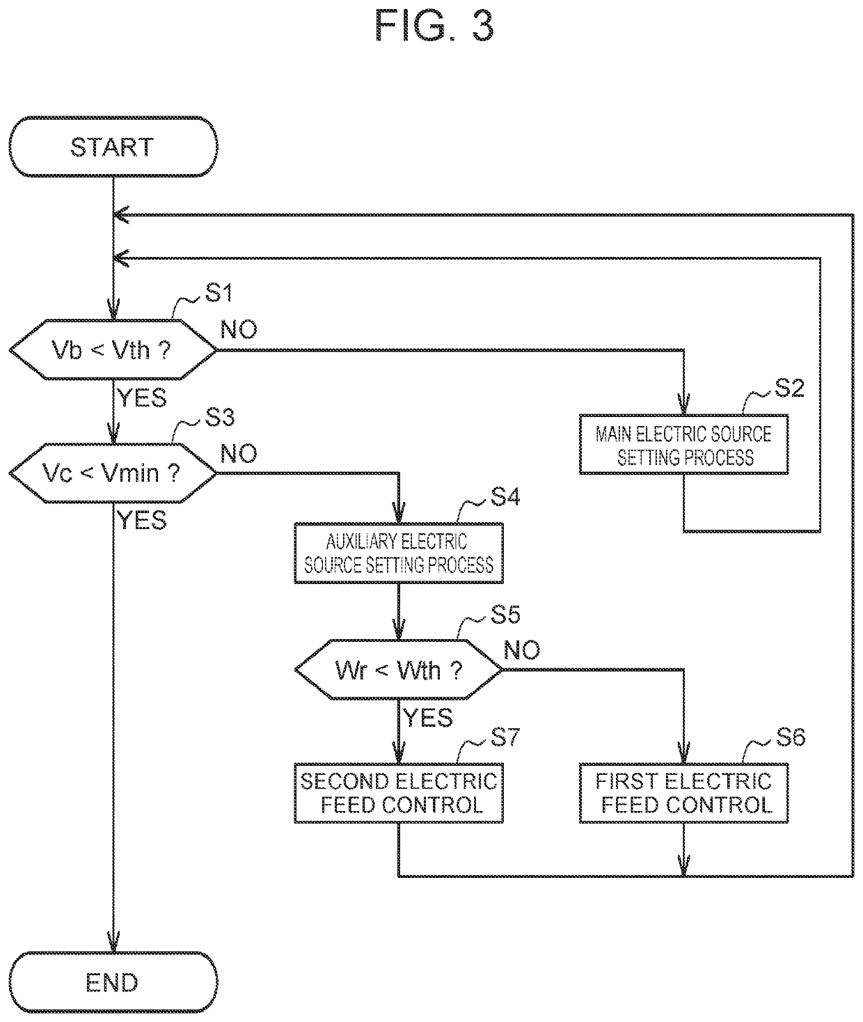
An auxiliary electric source device is provided on an electric feed path between a main electric source and an electric feed object of the main electric source. The auxiliary electric source device includes an auxiliary electric source. The electric feed object performs a minimal action of fulfilling a desired minimal function with electric feed from the auxiliary electric source when the main electric source has broken down. An electric source performance of the auxiliary electric source is set based on an electric power necessary for the minimal action.

Description

CROSS-REFERENCE TO RELATED APPLICATION[0001]This application claims priority to Japanese Patent Application No. 2019-042393 filed on Mar. 8, 2019, incorporated herein by reference in its entirety.BACKGROUND1. Technical Field[0002]The disclosure relates to an auxiliary electric source device and a steering device.2. Description of Related Art[0003]As a device that causes an electric feed object to act with electric feed from a main electric source and thereby fulfill a desired function, for example, there is a device that causes a motor to act with the electric feed from the main electric source and thereby fulfill a function to give rotation power of the motor to a steering mechanism of a vehicle as steering assist power in order to assist a steering operation by a driver (Japanese Patent Application Publication No. 2018-196203 (JP 2018-196203 A)).[0004]In JP 2018-196203 A, there is provided an auxiliary electric source device including an auxiliary electric source that backs up the...

Claims


Application Information

Patent Timeline
Patent Type & Authority Applications(United States)
IPC IPC(8): B62D5/04
CPCB62D5/0463B62D5/0409B60R16/02B60R16/03B62D5/04H02J9/06H02J9/068B62D5/046B62D5/0481
Inventor SHINODA, SATOSHISUGIYAMA, TOYOKI
Owner JTEKT CORP
Learn More