
Low drag hub for rotor

a rotor and low-drag technology, applied in the field of aircraft, can solve the problems of drag when traveling at high speed, various surfaces of rotary-wing aircraft, and limited forward airspeed of conventional rotary-wing aircraft, and achieve the effect of maintaining air flow

Active Publication Date: 2020-08-06
LOCKHEED MARTIN CORP
View PDF0 Cites 0 Cited by
  • Summary
  • Abstract
  • Description
  • Claims
  • Application Information

AI Technical Summary

Benefits of technology

The patent text describes a design for a rotary machine that has a smooth and continuous surface on the first rotor hub, which helps to maintain air flow. This design ensures that the machine operates efficiently and effectively without any interruptions in air flow.

Problems solved by technology

Conventional rotary-wing aircraft have a forward airspeed that is limited by a number of factors.
Among these factors is the existence of drag when traveling at high speeds.
Various surfaces on the rotary wing aircraft, both stationary and rotating, create drag during flight.

Method used


Image

  • Low drag hub for rotor
  • Low drag hub for rotor
  • Low drag hub for rotor

Examples


Embodiment Construction

[0019]A detailed description of one or more embodiments of the disclosed apparatuses are presented herein by way of exemplification and not limitation with reference to the Figures.

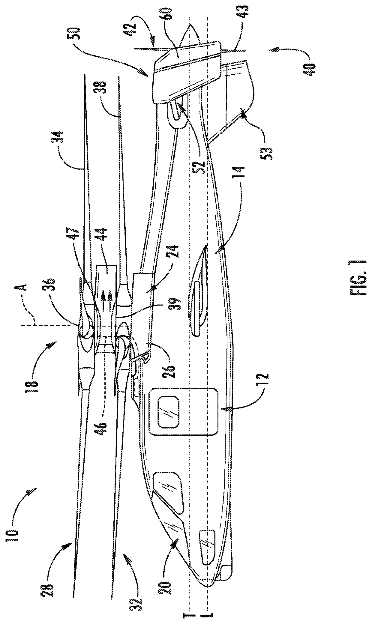
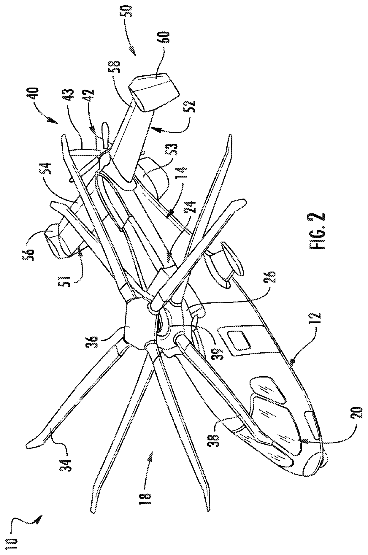
[0020]Coaxial rotors or “coax rotors” are a pair of helicopter rotors mounted one above the other on concentric shafts, with the same axis of rotation, but turning in opposite directions (contra-rotating). The rotor hub is one of the largest contributors to the vehicle drag, accounting for 25%-30% of the aircraft total drag. High drag limits maximum flight speed and reduces vehicle efficiency. Computational Fluid Dynamics (CFD) showed that the current hub has a large flow separation region, which leads to higher drag. One or more embodiments of the invention are configured to reduce hub system drag thereby enabling faster fight speed and provide less fuel burn for a given flight speed. This drag reduction is estimated to increase the maximum speed of the aircraft by 5 knots, according to an exemplary embo...


PUM


Abstract

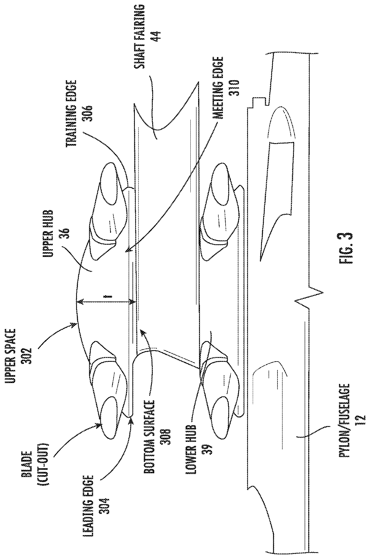
A rotor assembly includes a first rotor hub and a second rotor hub. The second rotor hub is coupled to the first rotor hub via a shaft fairing. The first rotor hub has a flat first surface coupled to the shaft fairing and a curved second surface opposite the flat first surface. The second rotor hub has a flat first surface on the lower side and a curved second surface opposite the flat first surface.

Description

BACKGROUND[0001]Exemplary embodiments relate to the art of aircraft, and more particularly, to a low drag hub for a coaxial rotor.[0002]Conventional rotary-wing aircraft have a forward airspeed that is limited by a number of factors. Among these factors is the existence of drag when traveling at high speeds. Various surfaces on the rotary wing aircraft, both stationary and rotating, create drag during flight. Drag has a direct effect on aircraft power requirements, range, and efficiency. Accordingly, it is desirable to increase an overall lift-to-equivalent-drag ratio (L / DE) to enhance an operational envelope of the rotary wing aircraft.BRIEF DESCRIPTION[0003]According to one or more embodiments, a rotor assembly is provided. The rotor assembly comprises a first rotor hub, and a second rotor hub coupled to the first rotor hub via a shaft fairing. The first rotor hub has a flat first surface coupled to the shaft fairing and a curved second surface opposite the flat first surface.[000...

Claims


Application Information

Patent Timeline
Patent Type & Authority Applications(United States)
IPC IPC(8): B64C27/10F04D29/18B64C27/32
CPCF04D29/181B64C27/10B64C27/32B64C11/02B64C11/48
Inventor MIN, BYUNG-YOUNGBOWLES, PATRICK ORMANDEWAKE, BRIAN ERNESTBATTISTI, MARGARET G.LORBER, PETER F.
Owner LOCKHEED MARTIN CORP
Learn More