Control system for self-moving platforms

a technology of control system and self-moving platform, which is applied in the direction of manipulators, non-electric variable control, instruments, etc., can solve the problems of insufficient detection of black, transparent or reflective obstacles by infrared sensors, and the operative limitations of this approach

Inactive Publication Date: 2020-08-06
TACTILE ROBOTS SRL
View PDF0 Cites 0 Cited by
  • Summary
  • Abstract
  • Description
  • Claims
  • Application Information

AI Technical Summary

Benefits of technology

The present invention is a self-moving robotized platform that can perform its main tasks. The main advantage of this invention is it meets all the important requirements of its design.

Problems solved by technology

The most important contraindication associated to this technology relates to the complexity of the processing, as they must substantially perform image recognition of scenes of a certain complexity, and such complexity is the greater the more the environments are not known a priori.
Both some operative limitations of this approach and some complexity factors depend on the technology of the sensors.
For example, the infrared sensors do not properly perceive the presence of black, transparent or reflective obstacles, while the ultrasonic sensors incorrectly perceive very thin obstacles, or having surfaces not perpendicular to the ultrasound wave.
In the case of use of vision sensors, instead, the complexity is in the estimation of distances, which is substantially impossible with monoscopic signals, and it is excessively complex with stereoscopic signals.
Then, the sensors necessary to the perception of a scene typically involves significant costs and energy consumption, and also require a considerable design complexity.
The complexity of required processing is further increased in the case of management of any contact that is not determined by the motion of the robot: for example, the case in which the robot is bumped or pushed, deliberately or accidentally, by another entity also in movement.
In general, it can be concluded that, to properly handle all the possible cases, the perception of sensors should ensure an omnidirectional coverage and provide a huge amount of information; and the processing required to synthesize a correct and reliable interpretation of events would end up to be, therefore, more and more complicated.
The development of self-moving robotized platforms, capable of moving on generic, non-pre-defined and non-infrastructured paths, at the state of the art, is still a research issue, which is susceptible, and in need, of further evolutionary steps, before becoming a technology mature enough and suitable to be offered commercially, at least on a medium scale.
In fact, if a platform collides with an obstacle, the drive torque that before the impact was sufficient to move the platform, becomes insufficient, or the motion undergoes an appreciable slowdown.
This approach is not deepened because, despite being advantageously applicable in a certain variety of situations, a general use has significant drawbacks related to the fact that it must be based on an accurate modeling of the inertial system of the same platform and of the land on which the platform moves.
It should however be noted that the intervention can take place only upon impact, and then the limitation of the damage may not always be sufficient.
However, there are no known applications in self-moving robotized platforms, where their use is finalized to the control of the ambulation.
In fact, it is not immediate and easy to conceive a command protocol, based on pressure signals, and able to control correctly, accurately and safely the ambulation of a self-moving robotized platform in a generic environment.
It is a critical factor since both the collisions and the manual thrusts, which may be caused by a human operator, can be excessively strong and, above all, they are manifested as a discontinuous “step” function in which the transition between the absence of pressure and significant pressure happens substantially in an instant.

Method used


Image

  • Control system for self-moving platforms
  • Control system for self-moving platforms
  • Control system for self-moving platforms

Examples


Embodiment Construction

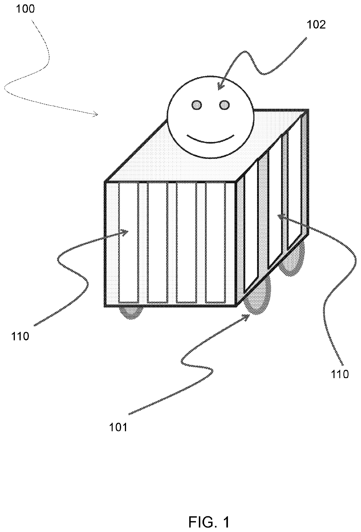
[0048]FIG. 1 provides an overall view of a self-moving robotized platform whose shape is roughly constituted by a parallelepiped with four vertical sides.

[0049]Obviously any type of shape is possible, however, the parallelepiped-shaped platform, in addition to allow a clear illustration of the inventive principles of the present invention, also constitutes one of the preferred shapes as it can be conveniently used as a trolley for the transport of payloads, and can also house all the components necessary for the operation of the same platform. In addition, it can be also suitable to accommodate the integration of eventual mechanisms functional in different applications.

[0050]With the number 100 it is then indicated, as a whole, the self-moving robotized platform according to the teachings of the present invention. However, the representation offered in FIG. 1 is essential and partial; they are highlighted only few elements, which are useful to illustrate some important features of s...


PUM


Abstract

The preferred field of application of the present invention concerns the control of the ambulation of the self-moving platforms, suitable to move in environments which are not necessarily known. In particular it is disclosed a technical solution that allows at the same time the manual control of the movements of such self-moving platforms (with good precision of control) and the management of the possible accidental collisions. This solution provides that the self-moving robotized platform is covered, at least partially and in its lateral surfaces with a particular coverage that acts simultaneously as a pressure sensor and as a shock-absorbing layer. They are therefore indicated some essential characteristics that make possible the definition of a set of manual intuitive commands, which are suitable to control the ambulation of such a platform. The system conceived in this way, in addition to ensuring a limitation of the damage in cases of collision, allows an operator to move a platform, irrespective of its weight, just by exerting slight thrusts in the desired directions; It will be also possible to give commands for movements along curved trajectories, or to impart rotations to the same platform.

Description

BACKGROUND OF THE INVENTION1. Field of the Invention[0001]The preferred field of application of the present invention concerns the control of the ambulation of the self-moving platforms, with particular reference to the development of robotized systems suitable to ambulate in environments which are not necessarily known.2. Brief Description of the Prior Art[0002]One of the most important aspects in the control of the ambulation of a robotized platform (or briefly, “a robot”) consists of the management of the possible bumps or contacts that can affect this robot when it moves, especially in an environment not completely modeled in the memory the robot itself. As it is in the case in which a moving robotized platform is activated and it can move freely, and therefore not on a predetermined path (such as a rail or a guide), within an environment that can also present obstacles variable in time: an environment as it can be a room of a house or an office.[0003]A first technological appro...

Claims


Application Information

Patent Timeline
Patent Type & Authority Applications(United States)
IPC IPC(8): B25J5/00B25J11/00B25J19/02
CPCB25J11/00B25J5/007B25J19/028G05D1/0212G05D1/0227B60W2300/40B25J13/081
Inventor TORNESE, RICCARDO
Owner TACTILE ROBOTS SRL
Why Eureka
Try Eureka