Multi-component safety needle cover

Active Publication Date: 2020-08-06
MOHR BERND +2
View PDF0 Cites 2 Cited by
  • Summary
  • Abstract
  • Description
  • Claims
  • Application Information

AI Technical Summary

Benefits of technology

The present invention provides a multi-component safety needle cover for use with injection devices, such as syringes. The cover is designed to prevent needlestick injuries by securely covering the needle before and after use. The cover consists of two cover members, an inner and an outer cover, that are rotatably coupled to each other. The inner cover member has a cavity to enclose the needle, and the outer cover member has a cavity to enclose the inner cover. The cover can be manipulated to expose the needle for use, and then permanently enclose it for safety. The cover is easy to manufacture and reduces the risk of re-use and inadvertent needle stick.

Problems solved by technology

A needlestick injury generally occurs in a medical environment, and particularly before or after use of a syringe or other injection device, when the user accidentally sticks the needle into himself or herself, or another person.
However, this type of safety syringe requires complex construction and is particularly expensive to manufacture.
Furthermore, such a safety design fails to address the possibility of injury occurring before the injection is given.
In particular, it is now recommended practice to not attempt to replace the sheath after the syringe has been used, because of the difficulty of placing the end of the needle accurately within the sheath.
It is thought that the act of trying to re-sheath the needle has in fact been the cause of a significant number of needlestick injuries, as such a method requires the use of two hands and the operator can be inaccurate.
Furthermore, the sheath can easily be removed again, so reoccurring injury is possible.

Method used


Image

  • Multi-component safety needle cover
  • Multi-component safety needle cover
  • Multi-component safety needle cover

Examples


Embodiment Construction

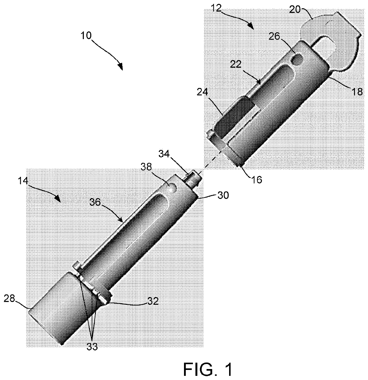
[0047]By way of overview, the present invention provides a multi-component safety needle cover for use with injection devices, such as syringes, wherein the safety needle cover is configured to prevent needlestick injury by permanently covering the needle after use thereof.

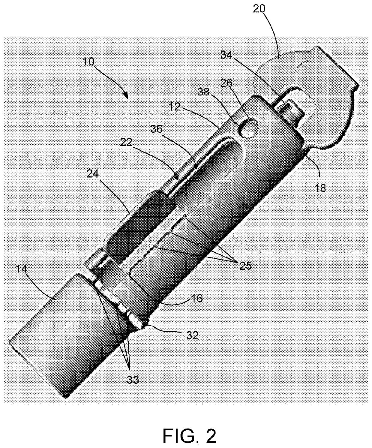
[0048]FIG. 1 is a perspective exploded view one embodiment of a safety needle cover 10 consistent with the present disclosure. The safety needle cover 10 is a relatively simple design comprising two cover members, an outer cover member 12 and an inner cover member 14 coupled to one another in a concentric manner (as shown in FIGS. 6 and 8). In particular, the outer cover member 12 includes a cavity shaped and sized to receive a majority of the inner cover member 14 within. The inner cover member also includes a cavity configured to enclose a needle extending from a delivery device to which the safety needle cover is directly coupled to. FIG. 2 is a perspective view of the safety needle cover 10 illustrating the ou...


PUM


Abstract

A safety cover configured to be coupled to an injection device and to provide a protective enclosure for a needle of the injection device, the safety cover including an outer cover member; an inner cover member coupled to the outer cover member in a concentric arrangement so that the outer cover member encloses at least a portion of the inner cover member, wherein the outer cover member is configured to move relative to the inner cover member from an unlocked position, in which the needle of the injection device is accessible for use, to a locked position, in which the outer cover member and the inner cover member are fixed at one another and the needle of the injection device is inaccessible, wherein the outer cover member includes a body that includes a proximal end, a distal end, and a cavity defined within the body.

Description

RELATED APPLICATIONS[0001]This application is a continuation of International application PCT / IB2018 / 000389 filed on Mar. 23, 2018, This application claims the benefit of, and priority to, U.S. Provisional Application No. 62 / 476,722, filed Mar. 24, 2017, U.S. Provisional Application No. 62 / 477,419, filed Mar. 27, 2017, U.S. Provisional Application No. 62 / 501,127, filed May 4, 2017, and U.S. Provisional Application No. 62 / 646,700, filed Mar. 22, 2018, the contents of each of which are hereby incorporated by reference herein in their entireties.FIELD OF THE INVENTION[0002]The present invention generally relates to safety devices, and, more particularly, to a multi-component safety needle cover for use with injection devices, such as syringes, wherein the safety needle cover is configured to prevent needlestick injury by permanently covering the needle after use thereof.BACKGROUND OF THE INVENTION[0003]As those within the medical field have developed an understanding that a variety of ...

Claims


Application Information

Patent Timeline
IPC IPC(8): A61M5/32A61M5/315A61M5/34
CPCA61M5/3202A61M5/348A61M5/321A61M5/31528A61M5/3216A61M2005/3217A61M5/50A61M5/5086
Inventor WILKE, TOBIASMOHR, BERND
Owner MOHR BERND
Why Eureka
Try Eureka