
Fluid pumping device

Active Publication Date: 2020-06-18
LIH YANN INDAL
View PDF17 Cites 0 Cited by
  • Summary
  • Abstract
  • Description
  • Claims
  • Application Information

AI Technical Summary

Benefits of technology

The technical effect of this patent is to provide a fluid pumping device that is better at sealing and is easier to use smoothly.

Problems solved by technology

However, the fluid is easy to spill to waste the fluid and result pollution.

Method used


Image

  • Fluid pumping device
  • Fluid pumping device
  • Fluid pumping device

Examples


Embodiment Construction

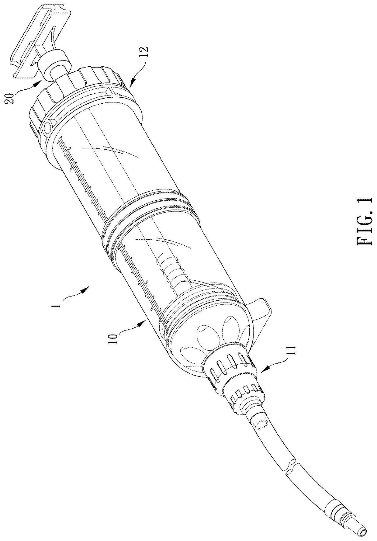
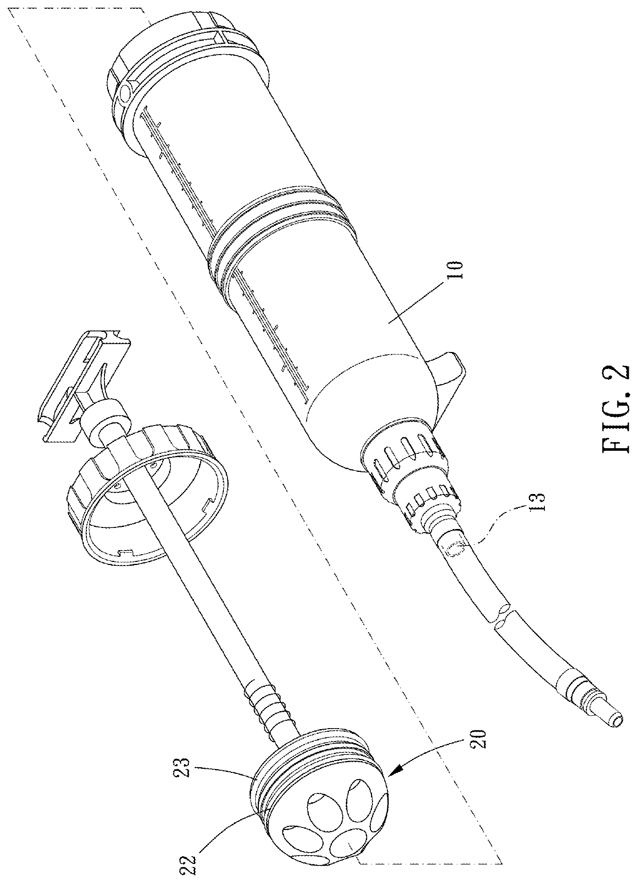
[0016]Please refer to FIG. 1 to FIG. 7, the fluid pumping device 1 of the present invention includes a barrel body 10 and a piston mechanism 20.

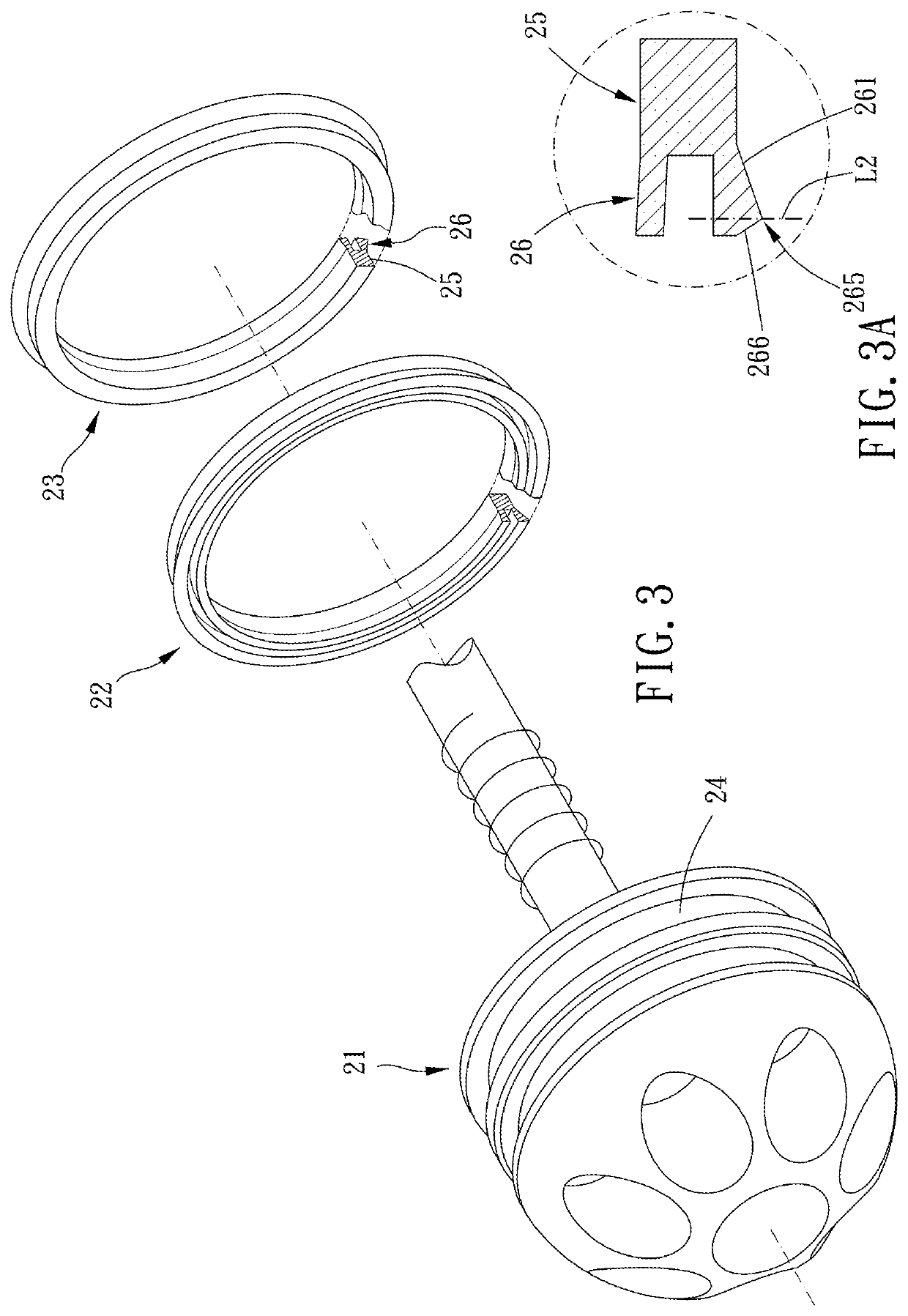
[0017]The barrel body 10 includes a first end portion 11 and a second end portion 12 located at an opposite side thereof from the first end portion 11. The first end portion 11 and the second end portion 12 are aligned along an axial direction L1. The first end portion 11 is formed with a flow hole 13. The second end portion 12 has an opening 14. The barrel body 10 further includes a cavity 15 communicating the flow hole 13 and the opening 14 respectively. The piston mechanism 20 includes a piston member 21, a first annular plug 22, and a second annular plug 23. The piston member 21 is arranged through the opening 14 and movably extends into the cavity 15. The piston member 21 has two annular grooves 24. The first annular plug 22 and the second annular plug 23 are disposed in the two annular grooves 24 respectively. The first annular plug 22...


PUM


Abstract

A fluid pumping device includes a barrel body and a piston mechanism. The barrel body has a cavity. The piston mechanism includes a piston member, a first annular plug, and a second annular plug. The piston member movably extends into the cavity. The piston member has two annular grooves where the first and the second annular plugs are disposed respectively. Each of the first the second annular plugs has an annular base section and an annular protrusion section. The annular protrusion section has a first outer annular abutting face. The annular base section has an outer annular base face. The first outer annular abutting face abuts against the inner wall of the cavity.

Description

BACKGROUND OF THE INVENTIONField of the Invention[0001]The present invention relates to a fluid pumping device.Description of the Prior Art[0002]To refill oil into a vehicle, the user usually opens the oil tank and injects oil into the tank by holding an oil bottle, such as brake fluid. However, the fluid is easy to spill to waste the fluid and result pollution.[0003]A revised fluid refilling device includes a pipe and a piston. The pipe is formed with a receiving space for receiving fluid. The piston is movable in the receiving space with respect to the pipe to push the fluid. Thereby, the user can inject fluid into the oil tank by operating the piston. A conventional piston has an O-ring sleeved thereonto. The O-ring abuts against the inner wall of the receiving space for sealing. However, when the piston moves, the O-ring slides too. Besides, the O-ring has little deformation so that gap may appear between the O-ring and the inner wall of the receiving space when the O-ring slide...

Claims


Application Information

Patent Timeline
IPC IPC(8): F04B43/067F02M37/14F04B9/14F04B9/103
CPCF02M37/14F04B9/103F04B13/00F04B9/14F04B43/067F04B53/14F04B53/143F04B53/16
Inventor LIAO, PO-LIN
Owner LIH YANN INDAL
Learn More