
Easily rennovated expansion joint for a concrete slab formwork system

Active Publication Date: 2020-06-18
LYNKS
View PDF13 Cites 0 Cited by
  • Summary
  • Abstract
  • Description
  • Claims
  • Application Information

AI Technical Summary

Benefits of technology

The disclosed embodiments provide an expansion joint for a concrete slab shuttering system that allows for easy and quick renewal when damage occurs. The longitudinal segments of the joint can be removed, replaced, and reassembled without the need for heavy operations like breaking the concrete and joints. Additionally, the expansion joint is designed to remain stable and prevent problems like cracks and breakages. The horizontal nesting of the longitudinal segments allows for transfer of vertical loads between them. The removable parts of the segments have complementary faces and profiles, which provide smooth surfaces for vehicles and reduce wear and shocks on the concrete slab. The longitudinal segments can be made of a polymer material, which makes them easy to abrade for optimal flatness.

Problems solved by technology

At the end of their working life, or when these shuttering systems and expansion joints are incorrectly positioned, the opening of the expansion joint after shrinkage of the concrete slab can give rise to shocks or jerk-like stresses that cause damage to the concrete and the longitudinal segments of the said expansion joint.

Method used


Image

  • Easily rennovated expansion joint for a concrete slab formwork system
  • Easily rennovated expansion joint for a concrete slab formwork system
  • Easily rennovated expansion joint for a concrete slab formwork system

Examples


Embodiment Construction

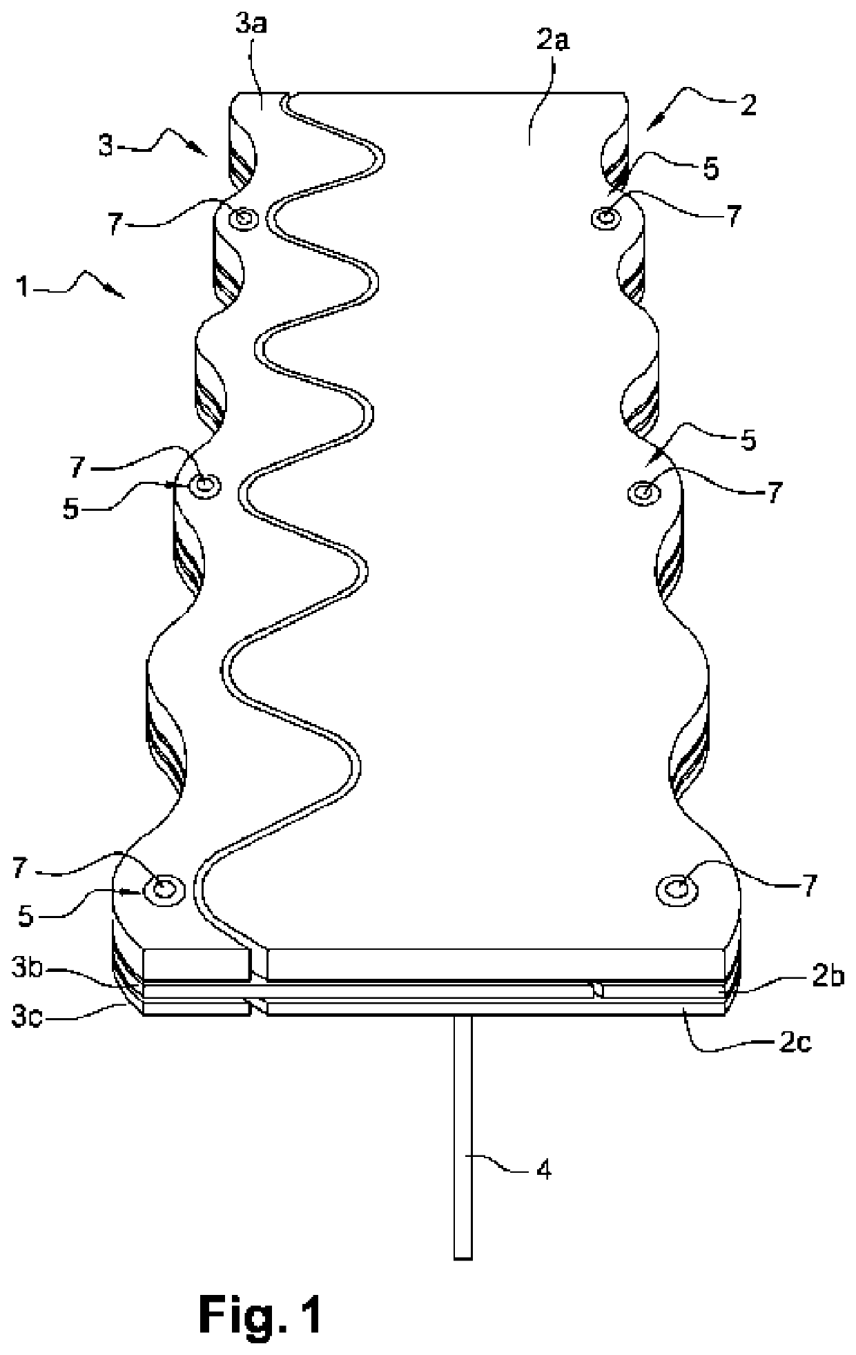
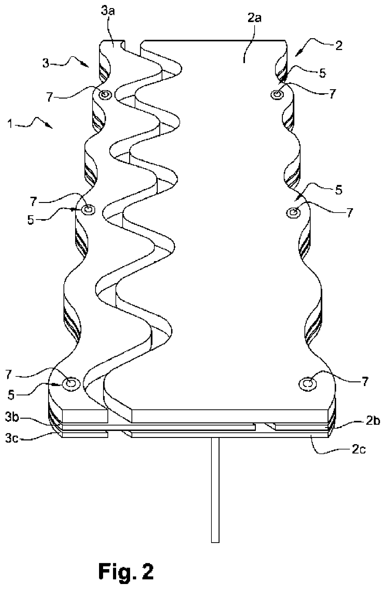
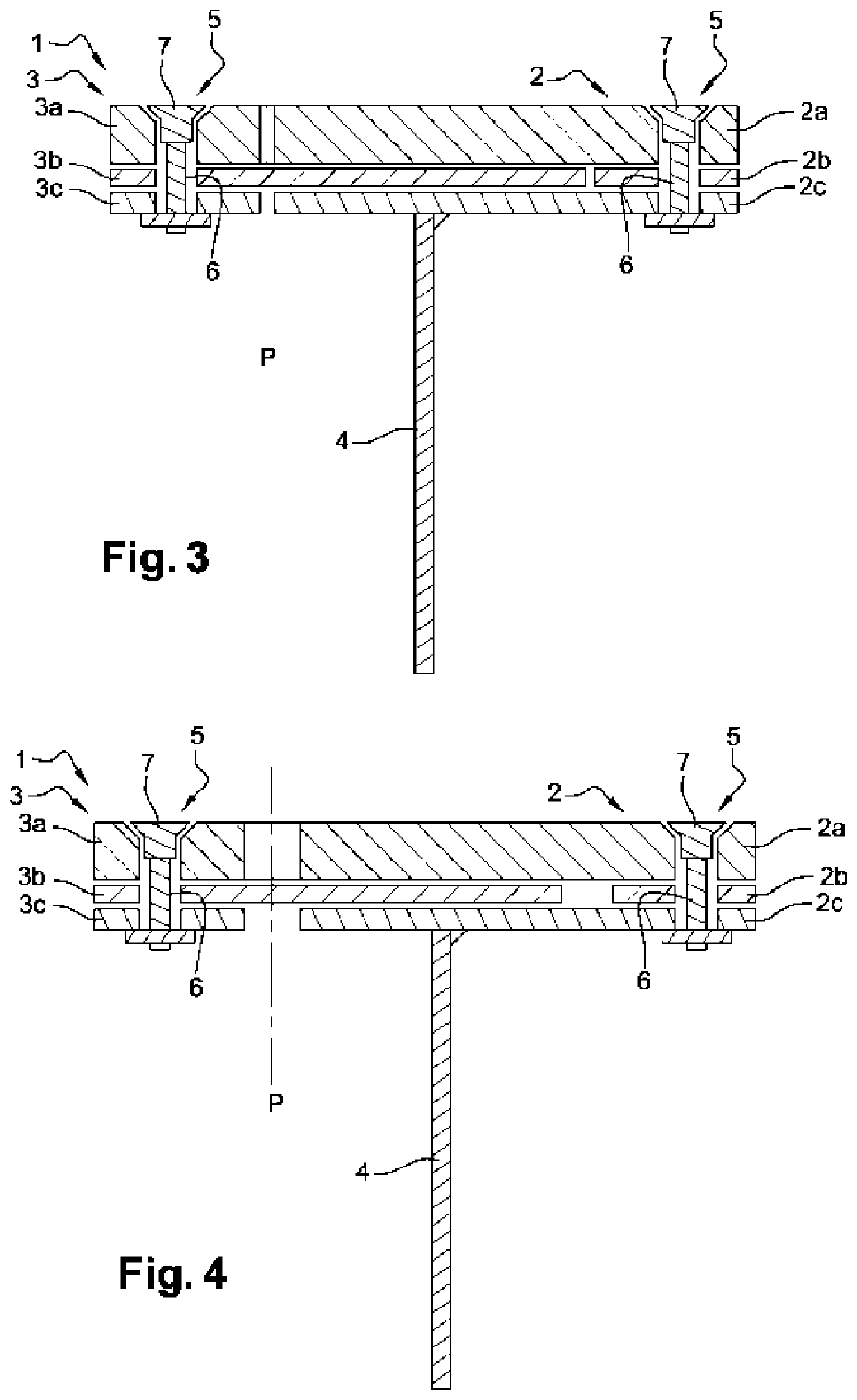
[0024]The described embodiments concern an expansion joint (1) for a shuttering system for concrete slabs that employs at least one vertical separation means between two adjacent concrete slabs, such as a plate, and that is used when necessary, for the pouring of the concrete, to divide the concrete slab into multiple parts, according to its surface area and its thickness, to create an air space necessary for the absorption of variations in the volume of a slab—under the action of shrinkage, for example.

[0025]With reference to FIGS. 1 to 4, the expansion joint (1) incorporates first and second longitudinal segments (2, 3) positioned side by side in the same horizontal plane, being intended to each be integral with an upper and horizontal edge of a concrete slab.

[0026]The first longitudinal segment (2) is preferably attached to a vertical separation means (4) between two adjacent slabs, for example a plate. The vertical separation means can be directly fixed, for example welded, unde...


PUM

PropertyMeasurementUnit
Fractionaaaaaaaaaa

Abstract

An expansion joint (1) for a concrete slab formwork system, said joint comprising first and second longitudinal elements (2, 3), arranged side-by-side in the same horizontal plane, and intended to each form an integral part with an upper and horizontal edge of a concrete slab, the first and second longitudinal elements (2, 3) comprise arrangements (5, 6, 7) opening on their upper horizontal walls and enabling at least a portion (2a, 3a) of each of the first and second longitudinal elements (2, 3) to be withdrawn for replacement thereof. The first longitudinal element (2) comprises a stack of three layers of material (2a, 2b, 2c), with an intermediate layer (2b) having a smaller width than that of the two other layers (2a, 2c) such that the first longitudinal element (2) has a U-shaped cross-section, and the second longitudinal element (3) comprises a stack of three complementary layers of material (3a, 3b, 3c), with an intermediate layer (3b) having a larger width than that of the two other layers (3a, 3c) so as to form a transverse projection that is able to fit in the recess of the U-shape of the first longitudinal element (2).

Description

TECHNICAL FIELD[0001]The present disclosure concerns the technical domain of shuttering systems for concrete slabs procuring an expansion joint between two adjacent slabs. The disclosure herein more particularly concerns a perfected expansion joint, notably in terms of ease of renovation.BACKGROUND OF THE DISCLOSURE[0002]In the domain of construction, and notably the domain of coverage of ground with concrete slabs, it is a well-known practice to use a shuttering system incorporating expansion joints between the slabs. In effect, it is commonplace to divide the concrete slab into multiple parts, according to its surface area and its thickness, to create an air space necessary for the absorption of the variations in volume of a slab—under the action of shrinkage, for example.[0003]A known shuttering system generally incorporates an expansion joint including the first and second longitudinal segments, positioned side by side in the same horizontal plane, and with each one being intend...

Claims


Application Information

Patent Timeline
IPC IPC(8): E01C11/10E01C11/08
CPCE01C11/08E04B2103/02E01C11/106
Inventor DE RIVAS, ARNAUD
Owner LYNKS
Learn More