
Extendable spool

a spool and extension technology, applied in the direction of pipe joints, adjustable joints, thin material handling, etc., can solve the problems of increased opportunities for errors or failures, inconvenient, time-consuming, and increased erosion of flow redirection through elbows or hoses, so as to reduce erosion, facilitate spooling, and reduce the effect of spooling

Active Publication Date: 2020-05-14
OIL STATES ENERGY SERVICES
View PDF0 Cites 0 Cited by
  • Summary
  • Abstract
  • Description
  • Claims
  • Application Information

AI Technical Summary

Benefits of technology

The extendable spool solves the problem of erosion and damage caused by changes in flow direction by extending the flow line instead of redirecting it. It can be used from small to large diameters, reducing the number of lines needed and setup time.

Problems solved by technology

Accounting for length variances on non-permanent, pressurized, fluid-flow lines can be accomplished by combining together multiple lines to achieve the desired length, but this is inconvenient, time-consuming, and creates additional opportunities for errors or failures.
However, flow redirection through elbows or hoses accelerates erosion, especially when there are particulates in the fluid and / or when the fluid is flowing at a high rate, as seen during hydraulic fracturing operations.
Another drawback of using flow redirection for length make-up is that the method is not easily scalable to larger diameters—the required wall thicknesses quickly make installation difficult at best, to impractical at worst; therefore, traditional flow redirection lines used to make up for length variances are, relatively speaking, smaller diameters.
One drawback of only being able to redirect flow with small diameter lines is that multiple redirected-flow lines must be used to account for length differences between large diameter lines.

Method used


Image

  • Extendable spool
  • Extendable spool
  • Extendable spool

Examples


Embodiment Construction

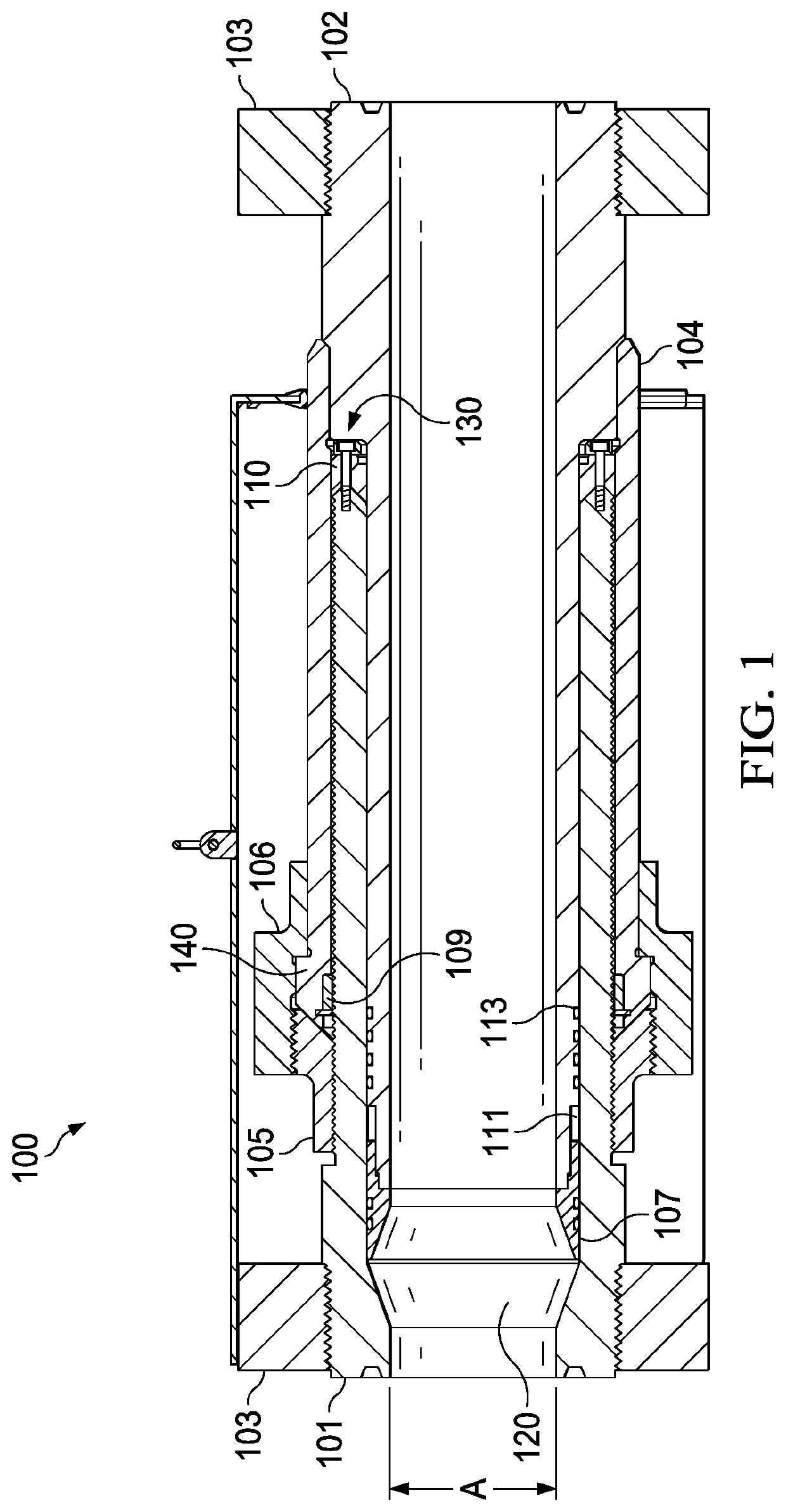
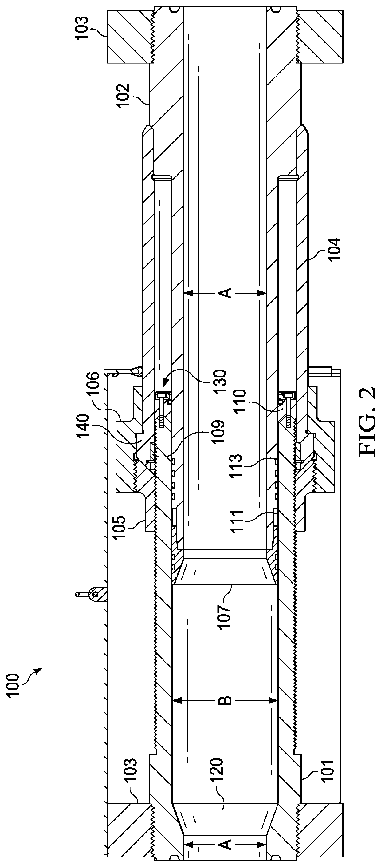
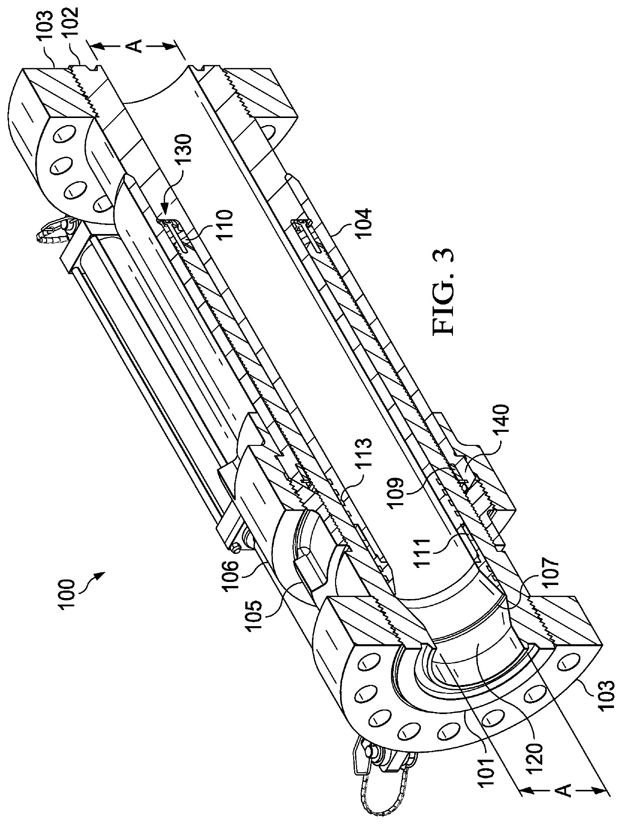
[0013]In an exemplary embodiment, FIGS. 1 and 2 schematically illustrate an extendable spool 100. The extendable spool 100 is a flow spool with a variable length. FIG. 1 illustrates the extendable spool 100 in fully contracted or compressed configuration, and FIG. 2 illustrates it in its fully extended configuration. The length is able to be varied continuously, rather than discretely, between the fully contracted and fully extended configurations. FIGS. 3 and 4 show isometric cutaway views of an embodiment of an extendable spool in fully contracted and fully extended positions.

[0014]The structure for two tubular sections of the extendable spool 100 through which fluid flows are described first. These sections are the threaded tube 101 and the inner tube 102. Each tubular section is designed to withstand pressurized fluids that may be used in hydraulic fracturing or other high-pressure downhole operations. The threaded tube 101 may have an inner diameter, referenced in FIG. 1 as ‘A,...


PUM


Abstract

An extendable spool is disclosed. The length of the extendable spool is able to continuously varied. The extendable spool accounts for length variances in flow lines by extending the flow line rather than redirecting the flow. Because the flow direction does not make any turns, erosion is minimized on both the extendable spool and downstream parts. The extendable spool is readily scalable from small diameters to large diameters. Because of this, it requires fewer lines and therefore less setup time to account for length differences between large diameter lines.

Description

[0001]This application is a continuation-in-part of U.S. application Ser. No. 16 / 184,510, filed Nov. 8, 2018.BACKGROUNDField of the Invention[0002]Accounting for length variances on non-permanent, pressurized, fluid-flow lines can be accomplished by combining together multiple lines to achieve the desired length, but this is inconvenient, time-consuming, and creates additional opportunities for errors or failures. Alternatively, length variances can be addressed by redirecting the flow through one or more turns until the desired length is achieved. Examples of this length make-up method are seen with hoses (via their flexible nature) and swiveling elbows (e.g., Chiksans). However, flow redirection through elbows or hoses accelerates erosion, especially when there are particulates in the fluid and / or when the fluid is flowing at a high rate, as seen during hydraulic fracturing operations. Erosion is accelerated not only on the parts redirecting the flow, but also on parts downstream....

Claims


Application Information

Patent Timeline
Patent Type & Authority Applications(United States)
IPC IPC(8): B65H16/06B65H75/22
CPCB65H16/06B65H2404/62B65H75/22F16L51/00F16L27/127F16L27/125B65H75/2209F16L27/1274
Inventor MCGUIRE, BOBARTHERHOLT, DANNY L.CLAXTON, MICKEYMULLINS, BLAKEGRASSMANN, DARIN
Owner OIL STATES ENERGY SERVICES
Learn More