
Improved modular structure curved magnetic guide for guiding the chain of a conveyor chain

a conveyor chain and magnetic guide technology, applied in the direction of conveyors, packaging, transportation and packaging, etc., can solve the problems of u-shaped upper body wear, periodic replacement, and special long and laborious operations, and achieve the effect of improving the modular structure, facilitating the mounting and dismounting of relative components and relative wearing parts, and improving the modular structur

Active Publication Date: 2020-05-14
REGINA CATENE CALIBRATE
View PDF0 Cites 0 Cited by
  • Summary
  • Abstract
  • Description
  • Claims
  • Application Information

AI Technical Summary

Benefits of technology

The patent text describes a new curved magnetic guide for guiding a conveyor chain that overcomes the drawbacks of previous solutions. The guide has an improved modular structure that makes mounting and dismounting operations easy and fast. It also has a reduced bulk, low cost, and can be used with different radius of curvature and length. Overall, this guide provides a simpler, more efficient, and cost-effective solution for guiding conveyor chains.

Problems solved by technology

As known, the U-shaped upper body is subject to wear and must be periodically replaced.
These operations are particularly long and laborious and require the stopping of the conveyor chain for a non-negligible time.
In the case in which it is necessary to carry out a maintenance intervention or replacement of some of the magnetic bodies it is necessary to dismount the entire guide and access the seat containing the magnetic bodies to be maintained or replaced and remount the guide, which are laborious operations that require long stopping times of the conveyor.

Method used


Image

  • Improved modular structure curved magnetic guide for guiding the chain of a conveyor chain
  • Improved modular structure curved magnetic guide for guiding the chain of a conveyor chain
  • Improved modular structure curved magnetic guide for guiding the chain of a conveyor chain

Examples


Embodiment Construction

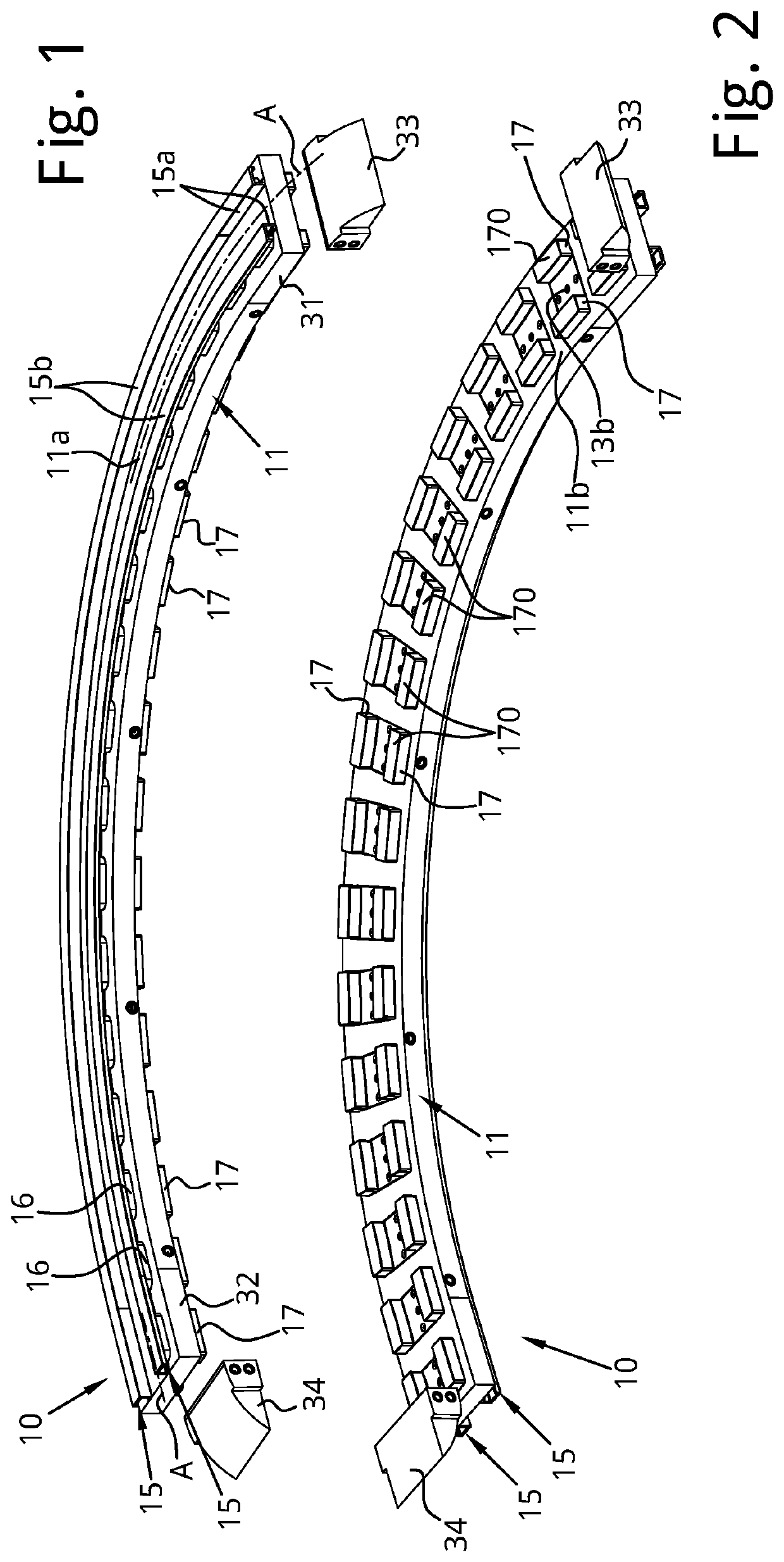
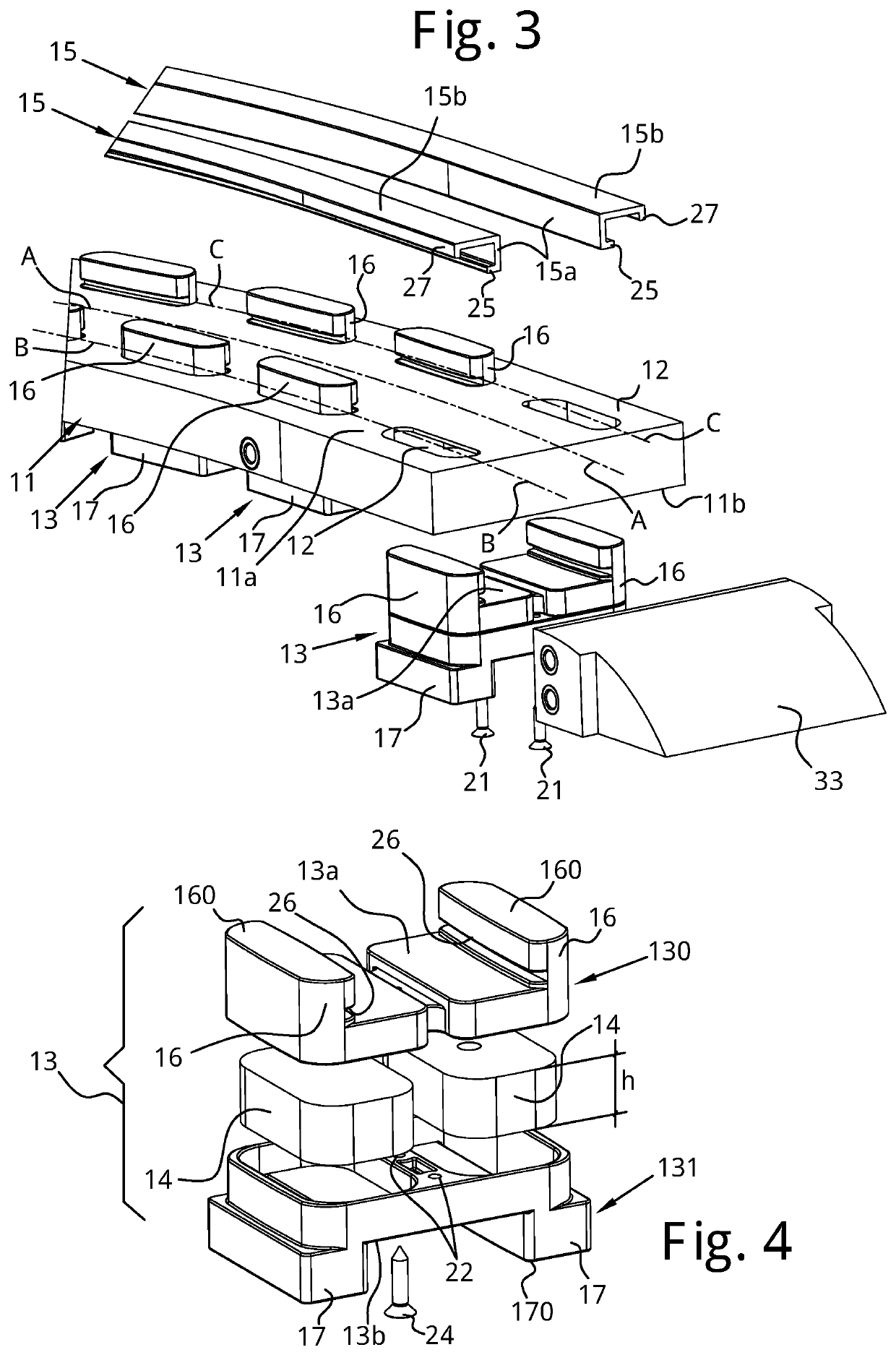
[0056]With reference to the attached figures, a curved magnetic guide 10 for a conveyor chain 100 is shown.

[0057]It should be specified that in the following description adjectives like “lower” and “upper” refer to the guide 10 considered in the usual conditions of use with respect to a generally horizontal support plane. Adjectives like “longitudinal” and “transversal” refer to the development of the guide 10 respectively along the guide path and transversally thereto.

[0058]In the present description the same or corresponding elements will be indicated with the same reference numeral.

[0059]The conveyor chain 100 is of the type known by those skilled in the art.

[0060]The conveyor chain 100 is only schematically represented in some of the attached figures.

[0061]The chain 100 is at least partially made of magnetisable material and comprises a plurality of links 101, which are hinged together at respective hinging portions 102 by means of respective pins 104 and each of which is equipp...


PUM


Abstract

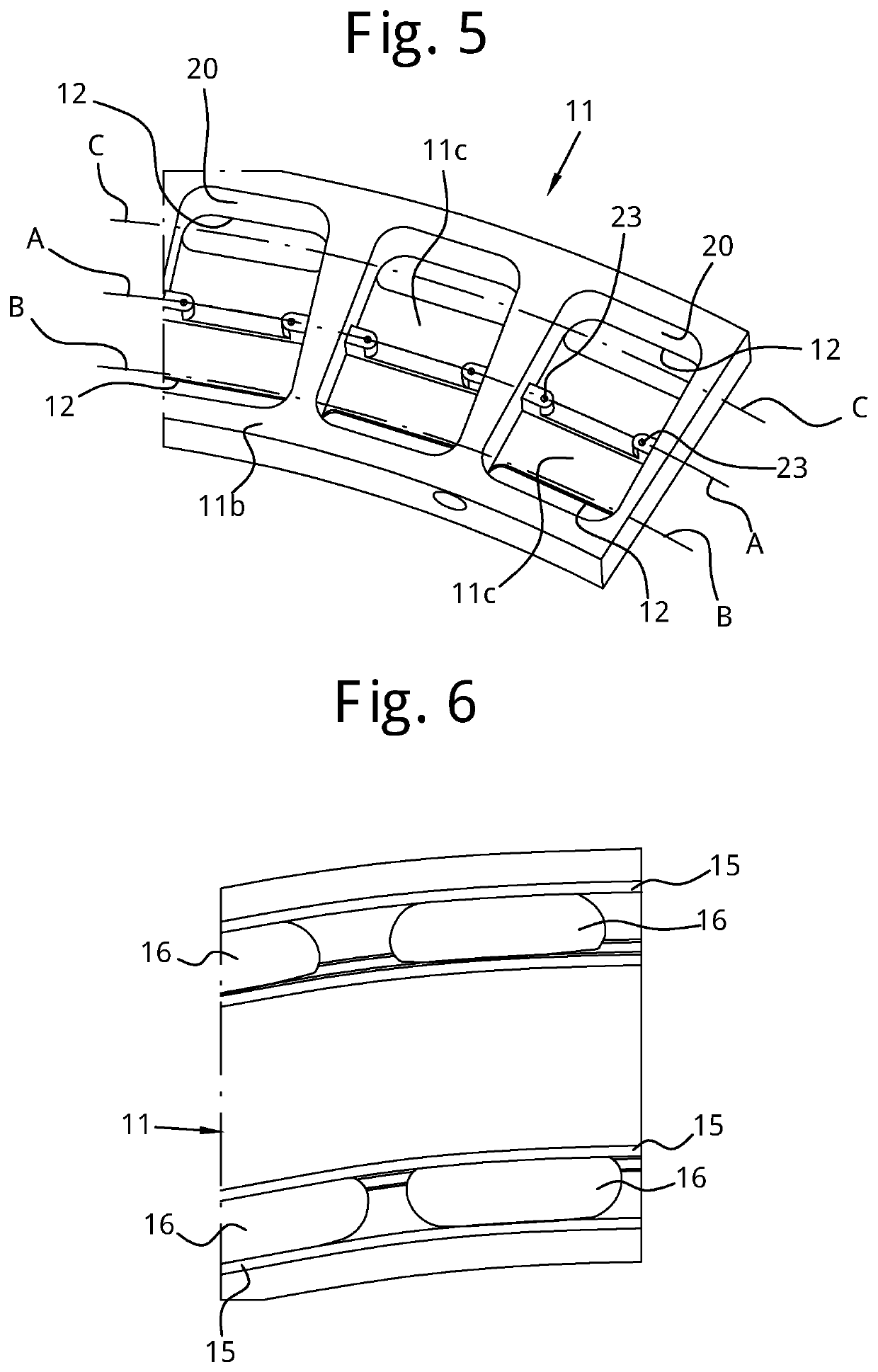
Curved magnetic guide for guiding the chain of a conveyor chain along a curvilinear transport direction including a pair of first guide profiles arranged spaced apart and extending in a continuous manner along a respective development direction concentric to the curvilinear transport direction, a support structure for supporting the first guide profiles having a plurality of box-shaped bodies, the box-shaped bodies being arranged in succession one after the other and spaced apart from one another along the curvilinear transport direction, where each of the box-shaped bodies houses at least one magnetic body and has an upper surface and a lower surface opposite one another, where the upper surface is provided with a pair of first constraining projections that are spaced apart and faced with distances between centers substantially equal to the distance between the development directions where the first constraining projections of the plurality of box-shaped bodies define two rows of first constraining projections that extend, spaced apart from one another, along a respective the development direction, where each of the first guide profiles is coupled with the first constraining projections aligned along one of the two rows, where the guide defines a forward guide for guiding the forward branch of the chain, the forward guide having a forward channel adapted for receiving the hinging portions of the links and which is laterally delimited by the first guide profiles of the at least one pair, where the first guide profiles each defines a sliding surface for the plate-shaped portion of the links to slide thereon, and where the magnetic bodies interact with the links to attract the links of the chain with the part of their plate-shaped portions against the sliding surfaces defined by the first guide profiles.

Description

TECHNICAL FIELD[0001]The present disclosure relates to a curved magnetic guide for guiding a chain of a conveyor chain having improved modular structure.BACKGROUND[0002]The term chain is meant to indicate in particular a so-called “table-top chain”, even more in particular a “table-top chain” for curved paths of the type comprising a plurality of links, which are articulated to one another by means of hinging and each of which has a hinging portion with the adjacent links and a generally plate-like portion, which extends transversally to the transportation direction of the chain and that defines a support surface for products to be transported.[0003]These chains are closed on themselves in a loop and wound around driving and idle wheels to form a conveyor for transporting products resting on the upper branch or forward branch of the chain itself.[0004]These chains, as known, are mounted along guides that comprise:[0005]a forward guide, along which at least one forward channel is for...

Claims


Application Information

Patent Timeline
Patent Type & Authority Applications(United States)
IPC IPC(8): B65G21/20B65G17/06B65G21/16
CPCB65G21/16B65G2207/30B65G17/066B65G21/2009B65G17/086B65G17/385
Inventor GARBAGNATI, CARLOCATTANEO, NORBERTO
Owner REGINA CATENE CALIBRATE
Learn More