
Auxiliary filter for the indoor unit of a Mini-Split heat pump

a technology for mini-split heat pumps and indoor units, which is applied in the direction of lighting and heating equipment, transportation and packaging, heating types, etc., can solve the problems of dust present in these shops that exceeds the design tolerance of an indoor unit, the indoor unit of mini-split heat pumps cannot operate well in commercial establishments, and the indoor unit of mini-split heat pumps cannot achieve the effect of reducing the carbon footprint, improving the tolerance of low air quality, and high efficiency

Active Publication Date: 2020-05-07
LEBLANC EDWARD BRIAN
View PDF0 Cites 0 Cited by
  • Summary
  • Abstract
  • Description
  • Claims
  • Application Information

AI Technical Summary

Benefits of technology

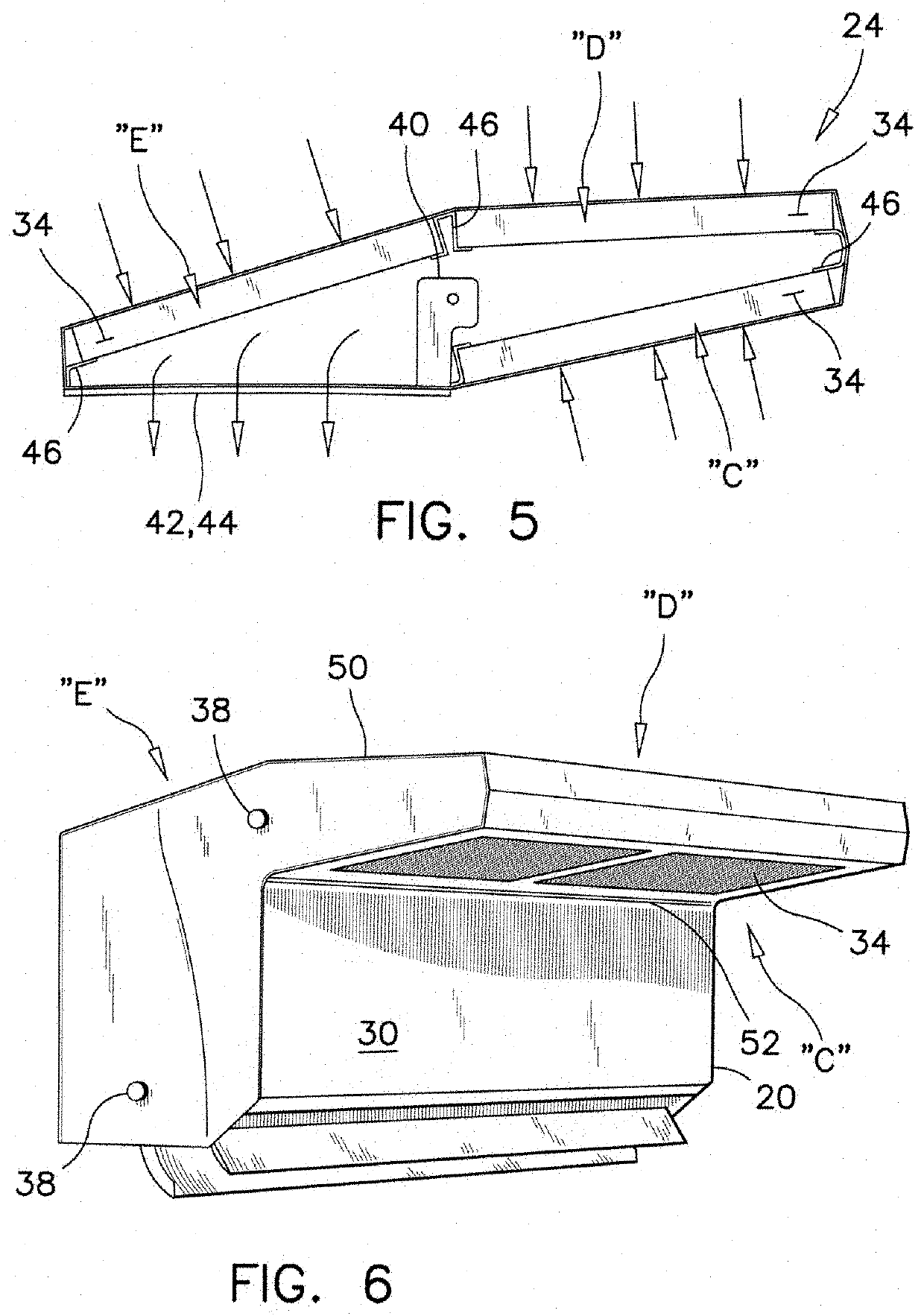
The present invention provides a method for improving the tolerance of a mini-split heat pump indoor unit to low-air quality. The method involves installing three stages of filtration in parallel above the air inlet opening of the indoor unit, each with an air flow capacity equivalent to the indoor unit's nominal air flow capacity. This additional filtration can provide a health benefit to people served and make the heat pump more efficient in environments with unpredictable air quality. An auxiliary filter can also be installed on the indoor unit, making its use in industrial and commercial settings possible.

Problems solved by technology

An indoor unit does not operate efficiently in a basement having a woodworking shop for example, or in a garage that is partly converted into a handyman shop.
The dust present in these shops exceeds the design tolerance of an indoor unit.
Similarly, these indoor units of mini-split heat pumps do not operate well in commercial establishments with heavy foot traffic, in manufacturing environments or in buildings located at remote locations, where periodic maintenance is difficult to schedule.
A search in the prior art has given a few results of auxiliary filters for heat exchangers, but none of these filters can be used without a complete redesign of modern mini-split indoor units.
Because of the limited space between the ceiling and the top of an indoor unit, the installations found in the prior art do not offer any suggestion to improve air filtration on an indoor unit of a mini-split heat pump.

Method used


Image

  • Auxiliary filter for the indoor unit of a Mini-Split heat pump
  • Auxiliary filter for the indoor unit of a Mini-Split heat pump
  • Auxiliary filter for the indoor unit of a Mini-Split heat pump

Examples


Embodiment Construction

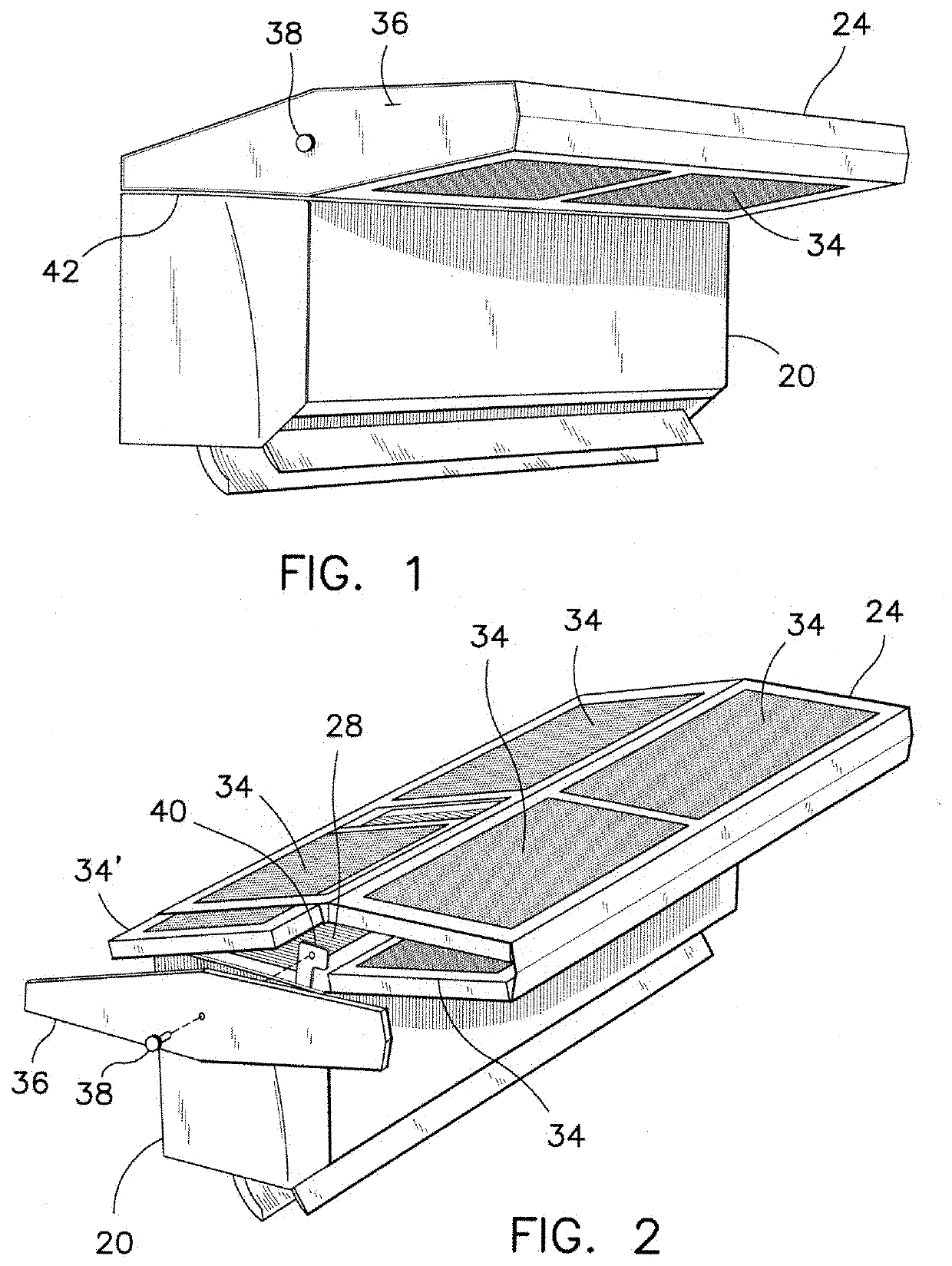
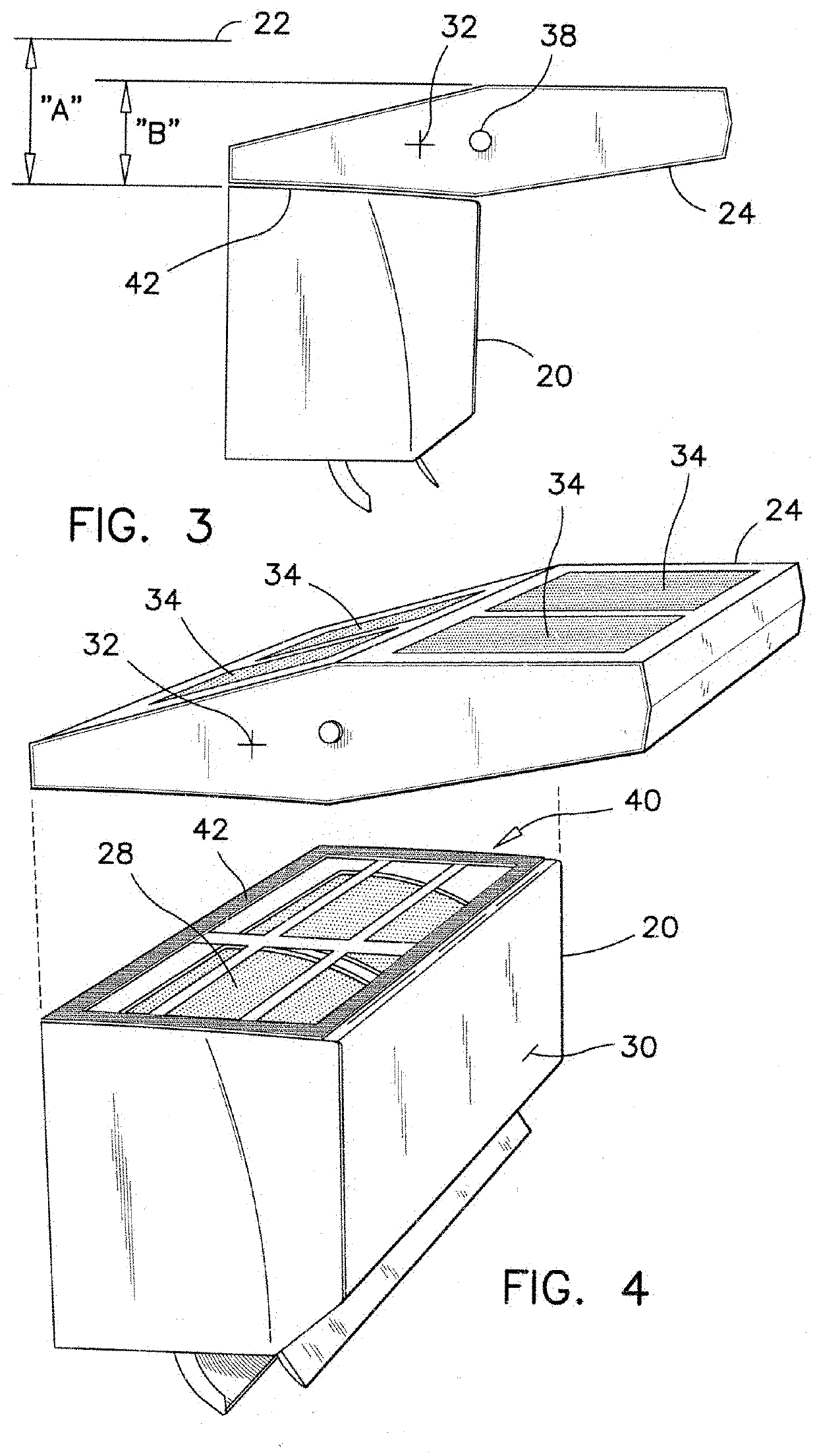
[0033]Referring firstly to FIGS. 1-4, the space “A” available between the top of an indoor unit 20 and a ceiling 22 is usually about 4-½ inches to 6 inches or more. The first preferred auxiliary filter assembly 24 has a shape of a visor sitting on the top of the indoor unit 20. The first preferred filter 24 has a total height “B” that is less than the available space “A”. In the first preferred embodiment the height “B” is about 4-¼ inches. The first preferred filter assembly 24 has a back portion overlapping the opening of the filter screen 28 of the indoor unit 20, and a front portion overhanging the front door 30 of the indoor unit 20, without preventing an operation of the front door.

[0034]The first preferred auxiliary filter 24 slides over the top of the indoor unit 20 and covers the air intake opening of the indoor unit 20 completely. The first preferred auxiliary filter 24 is retained on top of the indoor unit 20 by gravity or by magnetic tape, Velcro™ strips or similar attac...


PUM

PropertyMeasurementUnit
total thicknessaaaaaaaaaa
gravityaaaaaaaaaa
shapeaaaaaaaaaa

Abstract

The indoor unit of a mini-split heat pump has an auxiliary filter mounted atop the air inlet opening of the indoor unit. The auxiliary filter comprising three parallel filtering stages and each of these filtering stages having an air flow capacity equivalent to a nominal air flow rating of the indoor unit. The three filtering stages improve low-air-quality tolerance of a residential indoor unit of a mini-split heat pump, so that commercial and industrial users can also benefit from these high efficiency heat pumps to reduce their carbon footprint.

Description

[0001]This patent application claims the benefit of U.S. Provisional Application No. 62 / 766,782, filed Nov. 05, 2018.FIELD OF THE INVENTION[0002]This invention pertains to filters for heat pumps, and more particularly it pertains to filters for operating a residential heat pump in a dusty environment.BACKGROUND OF THE INVENTION[0003]Residential heat pumps, known as ductless mini-split heat pumps, are now associated with high efficiency, cost saving and excellent payback. Residential heat pumps have one or more indoor units that are installed relatively close to the ceiling. Heat pumps use a reverse Carnot™ cycle to extract heat from environmental air, to pump heated fluid into the heat exchangers of the indoor units and to circulate inside air through the heat exchangers.[0004]There is a double purpose for the installation of the indoor units near the ceiling. In addition to heating inside air through the heat exchanger, these units circulate warm air rising to the ceiling through t...

Claims


Application Information

Patent Timeline
Patent Type & Authority Applications(United States)
IPC IPC(8): F24F3/16F25B13/00F24F1/0011F24F1/0047F24F8/108
CPCF24F3/1603F24F1/0011F25B13/00F24F1/0047F24F1/0073F24F13/28F24F8/10F24F8/108B01D2221/16B01D2267/70B01D2267/30B01D2279/50B01D46/58
Inventor LEBLANC, EDWARD BRIAN
Owner LEBLANC EDWARD BRIAN
Learn More