Universal flying terrain vehicle

a terrain vehicle and universal technology, applied in the field of flying cars, can solve the problems of not being well-suited for road handling, not being able to convert the owner's terrain vehicle into an airplane, and being unable to adapt to the road handling of the vehicle,

Active Publication Date: 2020-05-07
LEVY & CIE
View PDF0 Cites 5 Cited by
  • Summary
  • Abstract
  • Description
  • Claims
  • Application Information

AI Technical Summary

Benefits of technology

[0009]It is therefore an object of the present invention to provide a universal airplane structur...

Problems solved by technology

There are several drawbacks with hitherto proposed flying cars.
One is that because both the terrain vehicle and the airplane form an integral structure, it is not possible for the owner of a terrain vehicle to convert his vehicle to an airplane.
Terrain vehicles are clearly optimized for driving on road surfaces and their engines and infrastructure are designed with this in mind, while conventional flying cars carry bulky wings and other components, which make them not well-suited for road handling.
To the extent that such vehicles must be driven for long distances on the ground, there is also a higher risk of damage not only to the terrain vehicle ...

Method used


Image

  • Universal flying terrain vehicle
  • Universal flying terrain vehicle
  • Universal flying terrain vehicle

Examples


first embodiment

[0033]FIG. 1 shows a flying vehicle 10 including an aerial platform 11 supporting wings 13, propellers 14 driven by a suitable thruster 15 coupled to a fuel supply shown schematically as 16. The aerial platform 11 also has a coupling mechanism 17 for coupling to a terrain vehicle 20. FIG. 2 shows a partial sectional view of the terrain vehicle 20 disengaged from the aerial platform 11.

[0034]The aerial platform 11 supports engines to create thrust, wings to create lift, control surfaces such as ailerons, rudder and height controls, an array of three undercarriages (primary and secondary landing gear having nose or tail wheels 21 and secondary wheels 22, respectively) to transport the weight during aircraft takeoff and landing, a servo control for the aircraft control surfaces and for the primary landing gear. The aerial platform 11 also has a chassis that is sufficiently massive to carry the combined weight of the aerial platform and the terrain vehicle and means for anchoring the t...

second embodiment

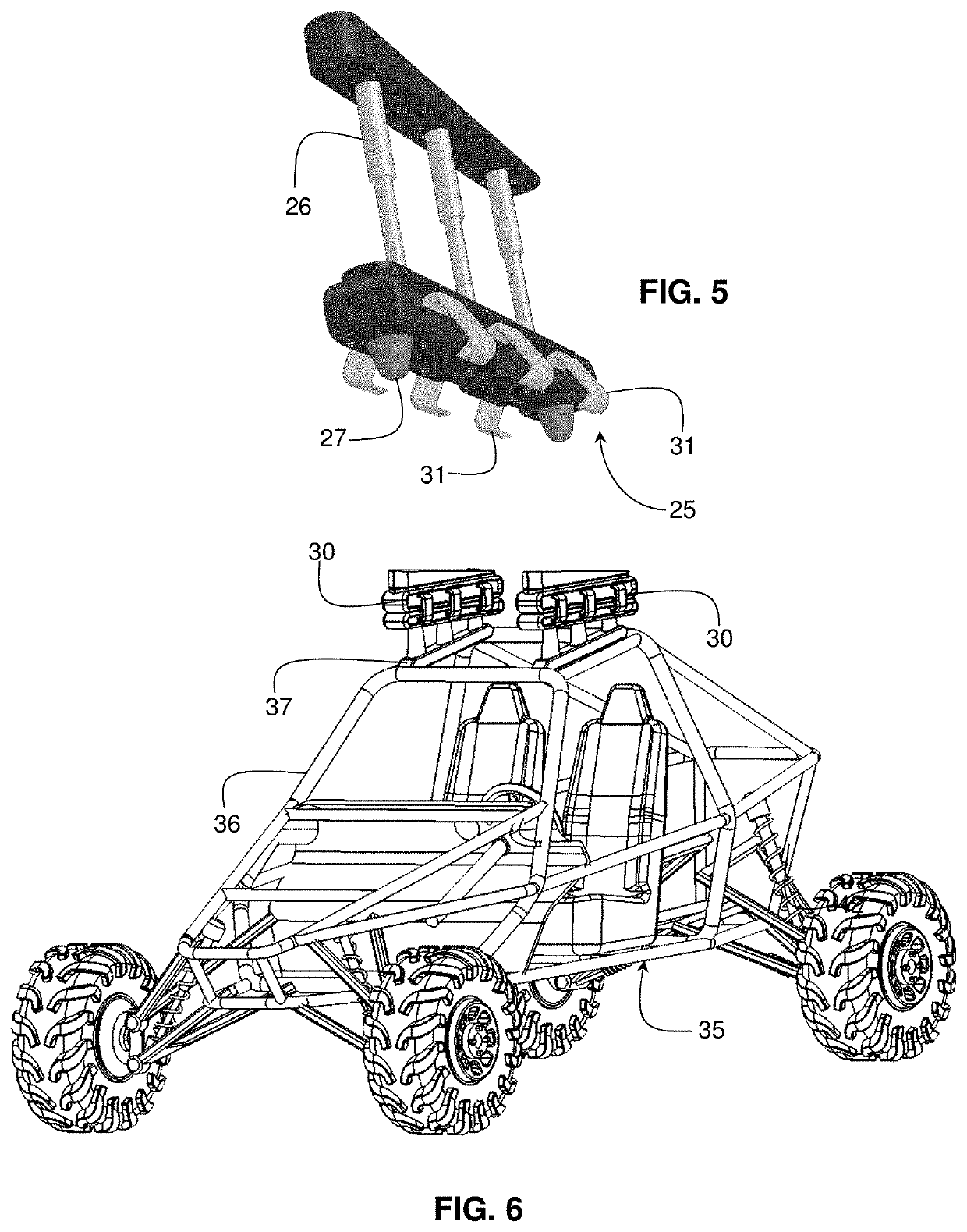
[0037]FIGS. 7 to 10 show a flying car 40 wherein the terrain vehicle 20 is coupled to a rotate wing aerial platform 41. The aerial platform 41 supports propellers 14 driven by a thruster 15 powered by a battery (constituting a fuel supply). The aerial platform 11 has latching mechanisms 25 as shown in FIG. 5 for coupling to a terrain vehicle 20. Also attached to the aerial platform 11 are adjustable legs 42 that serve as landing gear and each of which comprises at least two telescopic elements 43 that can be extended from an initial collapsed position shown in FIG. 7 during flight to an extended position shown in FIG. 9 on landing. Upon landing, the telescopic elements 43 are extended until the terrain vehicle 20 is lifted off the ground. The latch mechanisms 25 are then lowered via the pistons 26 so as to lower the vehicle to the ground and the clasps 31 are released in preparation for a ground phase.

[0038]The construction according to the invention also facilitates a business mod...


PUM


Abstract

A universal aerial platform (11, 41) supports lift elements (13, 14), thrusters (15), landing gear (21, 22) and a fuel supply (16) and has a coupling mechanism (17) external to the aerial platform for coupling to a terrain vehicle (20) so as to convert any suitably adapted terrain vehicle to a flying vehicle (10, 40). The terrain vehicle forms the cockpit of the flying vehicle. The terrain vehicle (20) includes flight controls that are automatically coupled to the airplane structure either wirelessly or by wires when the terrain vehicle is coupled thereto.

Description

FIELD OF THE INVENTION[0001]This invention relates to “flying cars” defined in Wikipedia™ as any type of personal air vehicle that provides door-to-door transportation by both road and air.BACKGROUND OF THE INVENTION[0002]As long ago as 1940, Henry Ford predicted that a combination airplane and motor car is imminent and indeed much progress has been made in recent years to realize this dream. Among several practical prototypes are the PAL-V ONE manufactured by PAL-V International B.V. shown at http: / / pal-v.com / , which employs a three-wheel two seat hybrid car and gyroplane having a foldable rotor mast that may be extended to convert the vehicle into a helicopter as described in US 2008 / 0067284, US 2014 / 0291440 and US 2016 / 0229245.[0003]Another company presently engaged in state-of-the-art flying cars is Aeromobil http: / / www.aeromobil.com / , which has developed a motor car having foldable side wings that unfold to form a conventional looking airplane. This is described in the patent l...

Claims


Application Information

Patent Timeline
IPC IPC(8): B64C37/00B64C25/10B64C13/16B64C13/04B64C13/50B64C13/26B64D27/02B64C27/00B64C31/036B64C25/00B64C7/00B60F5/02B60D99/00
CPCB64C13/16B64C13/503B64C25/10B64C13/042B60F5/02B64C13/26B64C2025/008B64C31/036B64C37/00B64C25/001B60D7/00B64D27/02B64C7/00B64C27/00B60D99/00
Inventor LEVY
Owner LEVY & CIE
Why Eureka
Try Eureka