
Agricultural harvester biomass estimating system

a harvester and biomass technology, applied in the field of agricultural combines, can solve the problems of inability to determine the height of the ground from which the standing crop is growing, inaccurate estimation of the amount of biomass to be harvested,

Active Publication Date: 2020-04-30
DEERE & CO
View PDF2 Cites 0 Cited by
  • Summary
  • Abstract
  • Description
  • Claims
  • Application Information

AI Technical Summary

Benefits of technology

The invention is a system that estimates the amount of unharvested crop in an agricultural field. It uses sensors on a vehicle to measure the crop and the previous crop that has been harvested. This information is then used to calculate the estimated biomass of the soil where the vehicle is located. This system helps the vehicle adjust its settings, such as the height of the header and the speed of the rotor, to optimize its performance.

Problems solved by technology

A common problem when harvesting agricultural crops is appropriately setting various machine processing parameters to accommodate the amount and type of crop material being harvested.
A particular problem for harvesting includes how to change agricultural harvester settings (i.e. settings of material processing mechanisms) to accommodate the changing mass and volume of crop material to be processed.
One drawback with this arrangement is the inability to determine the height of the ground from which the standing crop is growing.
This leads to inaccurate estimation of the amount of biomass to be harvested.

Method used


Image

  • Agricultural harvester biomass estimating system
  • Agricultural harvester biomass estimating system
  • Agricultural harvester biomass estimating system

Examples


Embodiment Construction

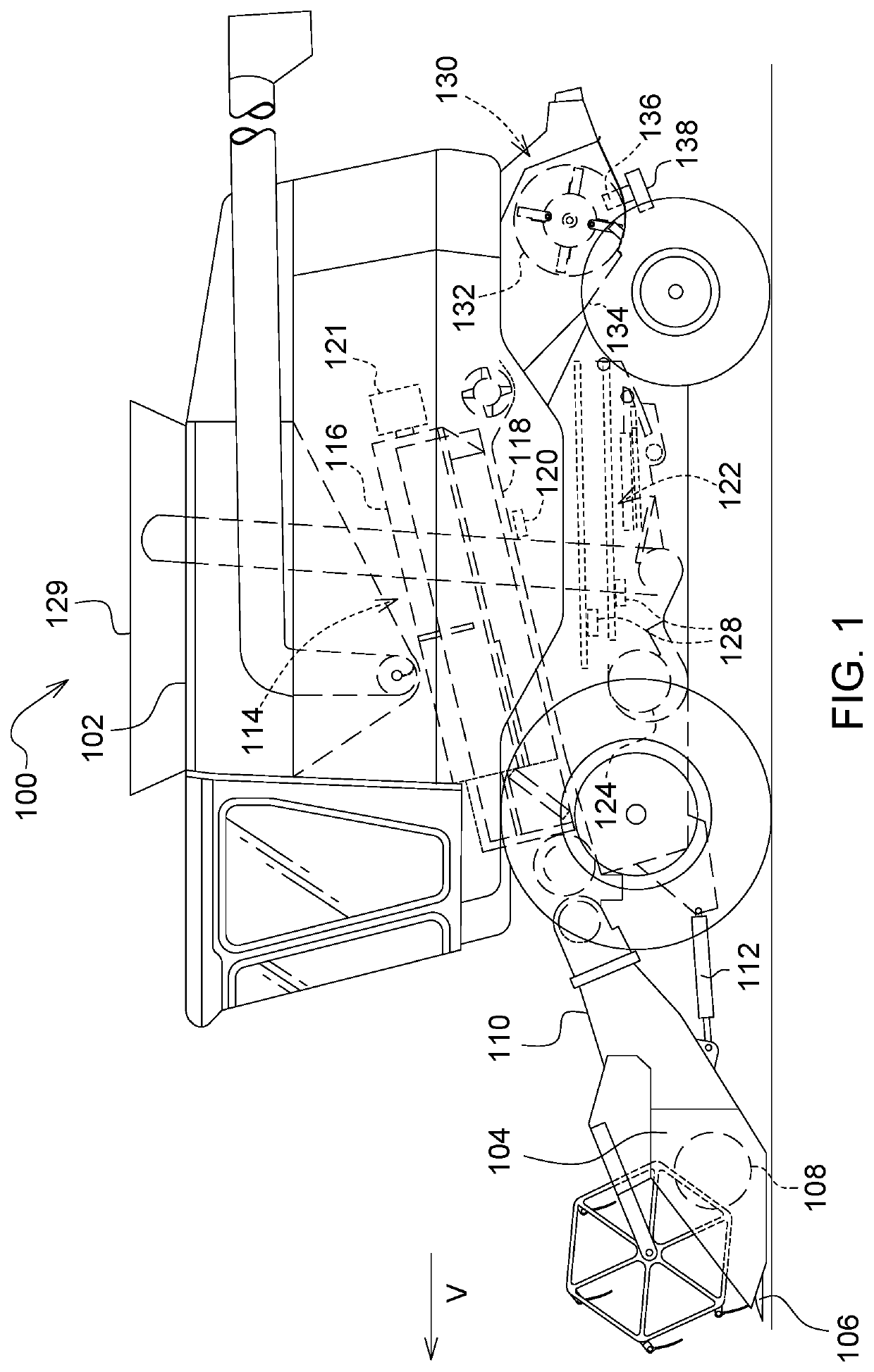
[0024]In FIG. 1 an agricultural harvester 100 is shown comprising a self-propelled agricultural harvesting vehicle 102 and an agricultural harvesting head 104 supported on the front of the agricultural harvesting vehicle 102.

[0025]A reciprocating knife 106 on the front of the agricultural harvesting head 104 severs the crop material from the ground. A conveyor system 108 on the agricultural harvesting head 104 carries cut crop material rearward to an inclined conveyor in a feederhouse 110. The inclined conveyor carries the cut crop material rearward and upward into the agricultural harvesting vehicle 102 for further processing.

[0026]The feederhouse 110 is pivotally coupled to the front of the agricultural harvesting vehicle 102 such that it can pivot up and down, thereby lifting and lowering the agricultural harvesting head 104 above the ground. Actuators 112 (here shown as hydraulic cylinders) are coupled to the feederhouse 110 and to the agricultural harvesting vehicle 102 to rais...


PUM


Abstract

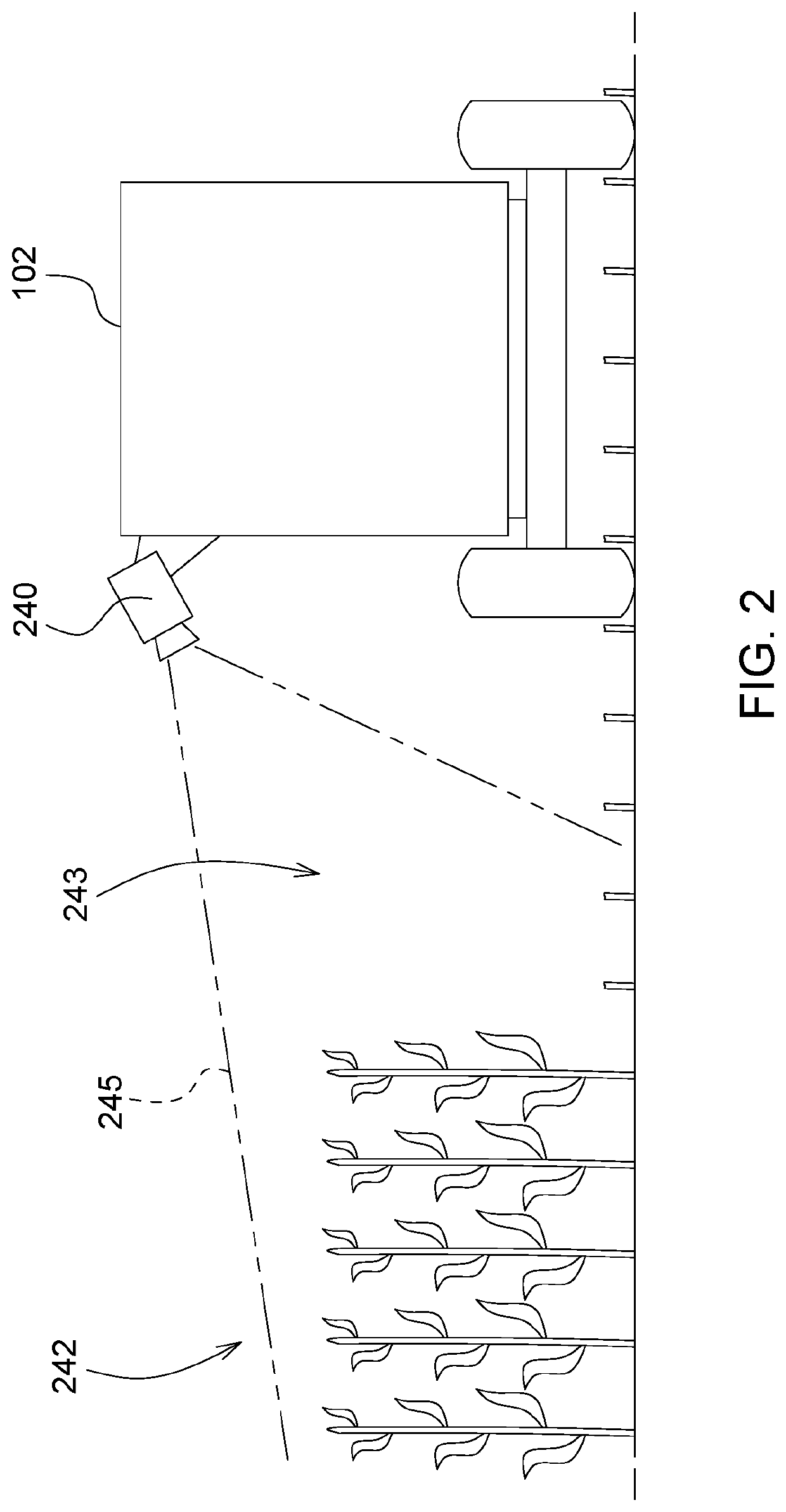
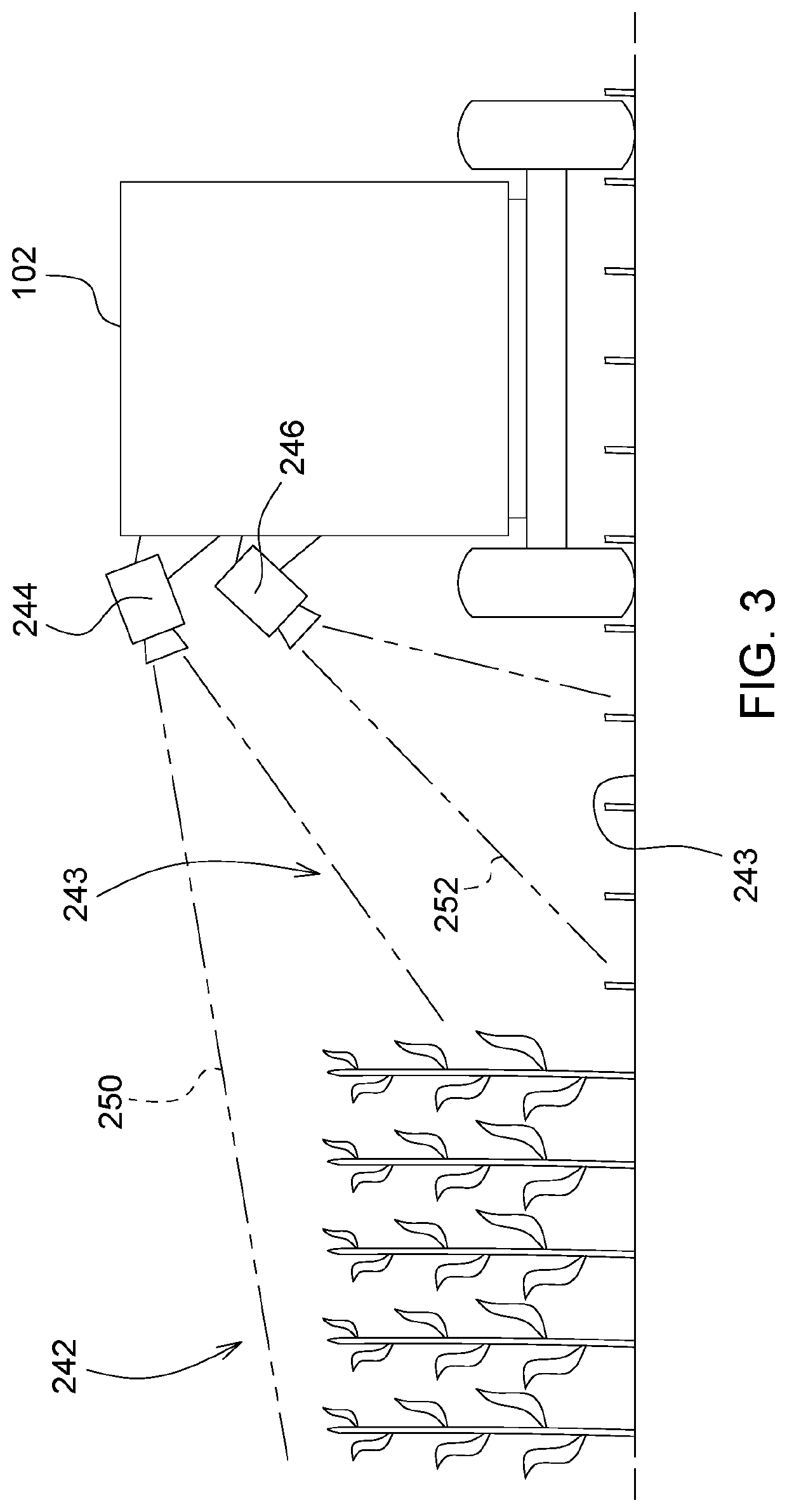
A biomass estimating system for an agricultural harvester includes a sensor arrangement disposed to sense standing crop adjacent to the agricultural harvester and disposed to sense a portion of ground adjacent to the agricultural harvester that has been previously harvested. An ECU receives signals indicating the standing crop and signals indicating the portion of the ground and calculates an estimated biomass of the standing crop based at least upon the signals indicating the standing crop and the signals indicating the portion of ground.

Description

FIELD OF THE INVENTION[0001]This invention relates generally to agricultural combines. In particular, it relates to systems for estimating biomass to be harvested and controlling combine machine settings responsiblyBACKGROUND OF THE INVENTION[0002]Agricultural harvesters such as combines or windrowers, travel through fields of agricultural crop harvesting the crop. In one common arrangement, agricultural harvesting heads extend forward from the spreading mechanism agricultural harvester to engage the plant stalks, sever them, and carry the severed crop into the body of the agricultural harvester itself for further processing.[0003]A common problem when harvesting agricultural crops is appropriately setting various machine processing parameters to accommodate the amount and type of crop material being harvested. A particular problem for harvesting includes how to change agricultural harvester settings (i.e. settings of material processing mechanisms) to accommodate the changing mass ...

Claims


Application Information

Patent Timeline
Patent Type & Authority Applications(United States)
IPC IPC(8): A01D41/127H04N23/90
CPCG01S17/89G06T2207/30252A01D41/127G06T2207/30188G01S13/89G06T7/0004A01D41/1271G06V20/188H04N23/90
Inventor VANDIKE, NATHAN R.GILMORE, BRIAN J.
Owner DEERE & CO
Learn More