Method for Sizing a Multi-ply Fiber Web and a Forming Section for a Multi-ply Fiber Web

a fiber web and multi-ply technology, applied in the field of multi-ply fiber web sizing and forming sections, can solve the problems of poor retention, low sizing response, complicated chemistry of the short circulation system, etc., and achieve the effect of eliminating or at least minimizing the disadvantages and problems of prior ar

Active Publication Date: 2020-04-16
VALMET TECH INC
View PDF0 Cites 3 Cited by
  • Summary
  • Abstract
  • Description
  • Claims
  • Application Information

AI Technical Summary

Benefits of technology

The patent aims to create a method for sizing a multi-ply fiber web and a forming section for a multi-ply fiber web that overcomes the problems and disadvantages of prior art. The technical effect is to provide a cost-effective solution for sizing a multi-ply fiber web that solves issues related to sizing agent distribution, outcome of sizing, strength property results, retention of fiber webs, runnability and chemistry of the short circulation of the fiber web.

Problems solved by technology

Sizing of a fiber web can also be cationic pulp sizing but as a disadvantages of this known method is low sizing response when large amounts of sizing agent is used, complicated chemistry of the short circulation system, poor retention and in large sizing agent dosages degradation of the formation.
Disadvantages of this known method are low sizing response and misting.
Disadvantageous in this method is that the sizing agent remains on the surface of the fiber web and thus may easily be flushed away and also that sizing agent distribution in the thickness direction of the fiber web is inclined as on the applied surface remains more sizing agent than reaches the other side and thus only minor strengthening is achieved, particularly with thick paper or board grades.

Method used


Image

  • Method for Sizing a Multi-ply Fiber Web and a Forming Section for a Multi-ply Fiber Web
  • Method for Sizing a Multi-ply Fiber Web and a Forming Section for a Multi-ply Fiber Web

Examples


Embodiment Construction

[0041]During the course of the following description like numbers and signs will be used to identify like elements according to the different views which illustrate the invention and its advantageous examples. In the figures some repetitive reference signs have been omitted for clarity reasons.

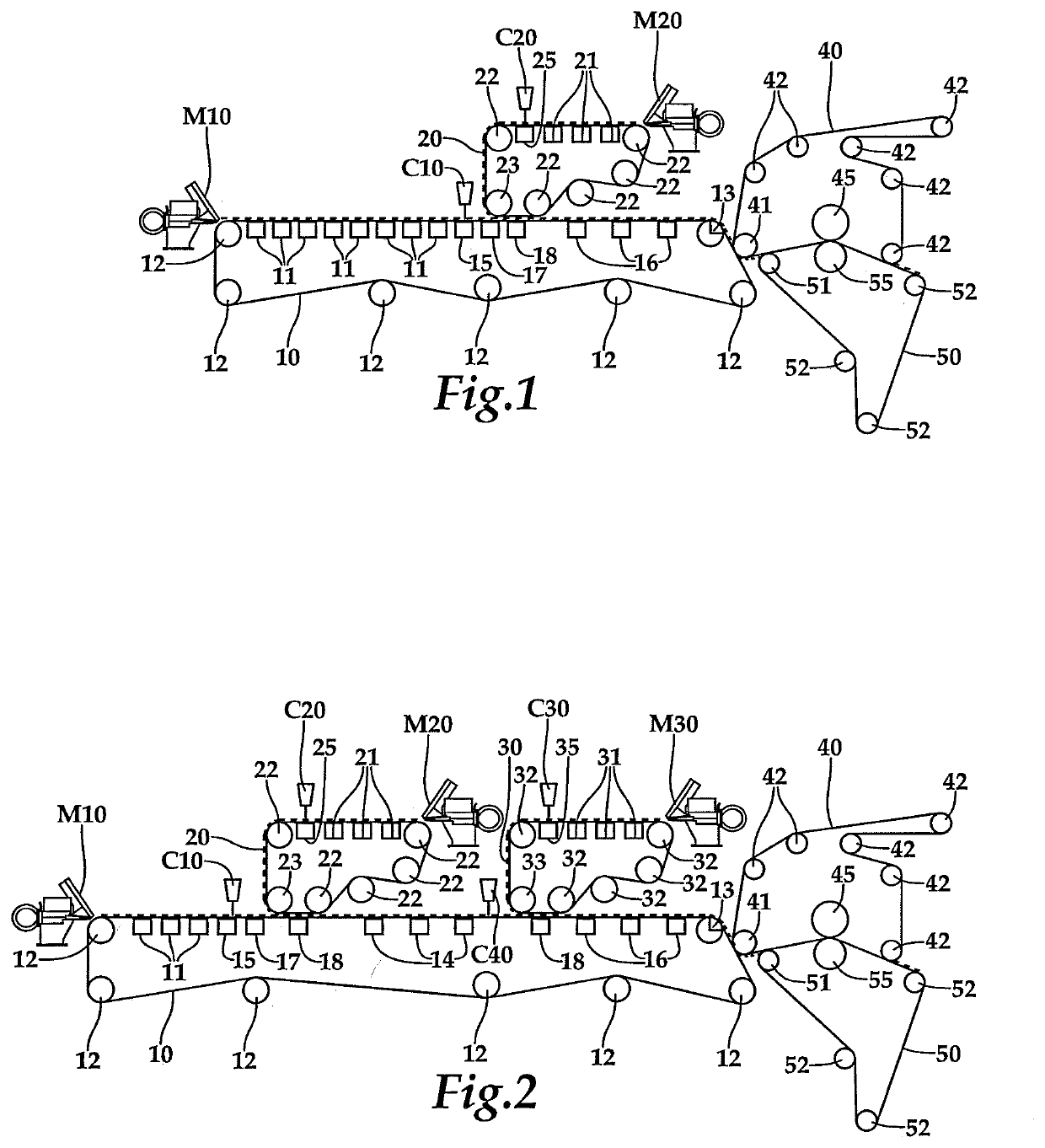
[0042]In FIG. 1 is shown an example of a forming section for a multi-ply fiber web, in this example for a two-layer fiber web. The forming section comprises two headboxs M10, M20 one for each layer, from which a stock suspension is fed to the forming unit for each layer beginning as one wire part comprising a wire 10 for the bottom layer of the multi-ply fiber web and a wire 20 for the top layer of the multi-ply fiber web. Each wire has rolls 12, 22 for guiding, tensioning and / or driving the wire 10, 20 as an endless loop. The stock suspension from the headboxs M10, M20 are first fed onto the wires 10, 20 and thereafter the stock on the wires is guided past water removal means 11, 21, 15, and ...


PUM

PropertyMeasurementUnit
Flow rateaaaaaaaaaa

Abstract

A method for forming a multi-ply fiber web in which least part of the sizing of the multi-ply fiber web is provided by applying sizing agent in the form of foam by a curtain type application device (C10, C20) in between at least two layers of the multi-ply fiber web in the forming section. The invention also relates to a forming section for a multi-ply fiber web having at least one twin-wire forming part formed between a wire (10) for the bottom layer and a wire (20) for the top layer of the multi-ply fiber web, where the layers are joined, and the treated layers combined. The forming section has a curtain type application device (C10, C20) for applying sizing agent in the form of foam in between two layers of the multi-ply fiber web in the forming section of a multi-ply fiber web production line.

Description

BACKGROUND OF THE INVENTION[0001]The invention relates generally to producing multi-ply fiber webs. Particularly the invention relates to a method for sizing a multi-ply fiber web in which at least part of the forming is done in a twin-wire forming part formed between a wire for the bottom layer of the multi-ply fiber web and a wire for the top layer of the multi-ply fiber web, in which the layers for the multi-ply fiber web are joined and treated layers combined in the twin-wire part, in which at least part of the sizing of the multi-ply fiber web is provided by applying sizing agent by a curtain type application device and to a forming section for a multi-ply fiber web. The invention also is relates to a forming section for a multi-ply fiber web having at least one twin-wire forming part formed between a wire for the bottom layer of the multi-ply fiber web and a wire for the top layer of the multi-ply fiber web, in which twin-wire part, the layers for the multi-ply fiber web are j...

Claims


Application Information

Patent Timeline
IPC IPC(8): D21H27/34D21F9/00D21H21/16D21H23/48
CPCD21H23/48D21F9/006D21H21/16D21H27/34D21H19/34D21H19/14D21H27/30D21H21/56D21H21/28D21H23/30D21F11/002D21F11/04
Inventor PIETIKÄINEN, REIJOPOIKOLAINEN, ANTTICECCHINI, JUANVIRKKUNEN, TEUVO
Owner VALMET TECH INC
Why Eureka
Try Eureka