
Lens with asymmetric optical zone to increase defocus image area

Inactive Publication Date: 2020-04-09
BRIGHTEN OPTIX CORP
View PDF0 Cites 1 Cited by
  • Summary
  • Abstract
  • Description
  • Claims
  • Application Information

AI Technical Summary

Benefits of technology

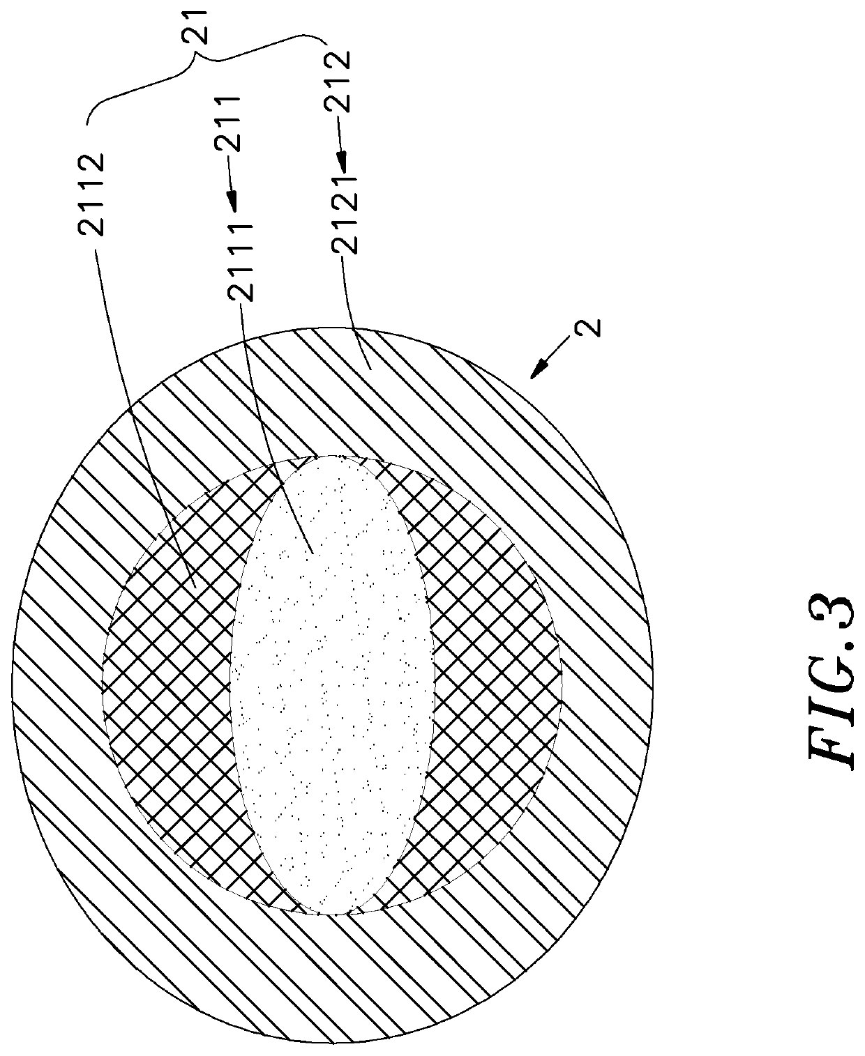
The present invention is about a special contact lens that can slow down the progression of myopia (nearsightedness) in children. The lens has two different optical areas: a central optical area that provides clear vision and a peripheral optical area that creates a blurred image. The lens also has an elliptical asymmetric optical zone that is designed to provide clear vision and a defocus area that creates a blurred image. The asymmetric optical zone is formed with a curved shape that makes it comfortable for the wearer and reduces the feeling of foreign body. This lens design can help to slow down the development of myopia in children by inducing myopic retinal defocus.

Problems solved by technology

However, the wearer must suffer a short adaptation period when initially wearing the peripheral defocusing lens.
Current peripheral defocus lens designs consist of a circular optical zone of either a concentric or annulus rings, the small optical zone diameter of these lens designs significantly degrade the wearer's ability to focus at the horizontal para-central visual field, for example during reading or horizontal visual search tasks.
For this reason, the conventional peripheral defocusing lens may impact the visual performance of wearing and even affect the safety of the wearer.
Therefore, how to develop new lens to solve the above-mentioned problems is a key issue for the manufacturers in this industry.

Method used


Image

  • Lens with asymmetric optical zone to increase defocus image area
  • Lens with asymmetric optical zone to increase defocus image area
  • Lens with asymmetric optical zone to increase defocus image area

Examples


Embodiment Construction

[0011]The following embodiments of the present disclosure are herein described in detail with reference to the accompanying drawings. These drawings show specific examples of the embodiments of the present disclosure. It is to be understood that these embodiments are exemplary implementations and are not to be construed as limiting the scope of the present disclosure in any way. Further modifications to the disclosed embodiments, as well as other embodiments, are also included within the scope of the appended claims. These embodiments are provided so that this disclosure is thorough and complete, and fully conveys the inventive concept to those skilled in the art. Regarding the drawings, the relative proportions and ratios of elements in the drawings may be exaggerated or diminished in size for the sake of clarity and convenience. Such arbitrary proportions are only illustrative and not limiting in any way. The same reference numbers are used in the drawings and description to refer...


PUM


Abstract

A lens with elliptic asymmetric optical zone to increase defocus image area is disclosed. The lens includes a central optical area to pass light to image on central imaging area of retina; a peripheral optical area formed around the central optical area and configured to pass light to image on a peripheral image blurring area on peripheral of the central imaging area; an elliptic asymmetric optical zone formed on the surface of the central optical area and configured to pass light to clearly image on the central imaging area; and a defocus area formed on a portion of the central optical area other than the asymmetric optical zone. The defocus area can be used to increase defocus image area of the central imaging area, to extend a range of the optical area having defocus effect on the retina without the need to excessively increasing the defocus power of the lens.

Description

BACKGROUND OF THE INVENTION1. Field of the Invention[0001]The present invention relates to a lens with an asymmetric optical zone to increase a defocus image area. More particularly, the lens includes an asymmetric optical zone formed on a surface of a central optical area thereof and configured to pass light to clearly image on a central imaging area of retina, and a defocus area formed on a portion of the central optical area other than the asymmetric optical zone and configured to increase the defocus image area of the relative central imaging surface area, so that the defocus area can be maximize to slow myopia progression.2. Description of the Related Art[0002]Generally, in order to correct myopia, most people wear glasses, contact lenses, orthokeratology lenses, or undergo a surgical procedure to permanently and safely correct their myopia. In recent years, manufacturer develops contact lens with a peripheral defocusing area for effectively reducing myopia progression, and suc...

Claims


Application Information

Patent Timeline
IPC IPC(8): G02C7/02G02B3/02G02C7/04
CPCG02C7/027G02C2202/24G02C7/063G02B3/02G02C7/044G02B3/10G02C7/042G02C7/104
Inventor WU, I-TSUNG
Owner BRIGHTEN OPTIX CORP
Learn More