
Solar tracking sensor based on fiber light guidance

Active Publication Date: 2020-03-19
JIANGSU UNIV
View PDF0 Cites 0 Cited by
  • Summary
  • Abstract
  • Description
  • Claims
  • Application Information

AI Technical Summary

Benefits of technology

The present invention is a solar tracking sensor that combines fine-positioning and coarse-positioning modules to expand the tracking scope, increase tracking precision, and reduce the cost of the system. It uses optical fibers to detect sun position, and when the sun moves at a small angle, the sensor is able to accurately track it. By combining the two modules, the sensor becomes more sensitive and efficient, and requires fewer components, resulting in lower costs.

Problems solved by technology

However, the solar energy also has the disadvantages of uneven distribution and intensity, which increase the difficult of the development and utilization of the solar energy.
The accuracy of the first two is low and the stability is poor.
Although cylinder configuration shows improvement on accuracy, the tracking range is limited.
The scheme is based on the cosine relation of sunlight angle and the incoming energy to optical fibers, and it is difficult to avoid the influence of stray light and other interference on the results.
In addition, the solar light collection ability of a single optical fiber is limited, and owing to the limits of the numerical aperture, OPS should be applied to assist in positioning, the control system is complex, and the cost would be high.
Such tracking systems are generally complicated, and the cost is high.

Method used


Image

  • Solar tracking sensor based on fiber light guidance
  • Solar tracking sensor based on fiber light guidance
  • Solar tracking sensor based on fiber light guidance

Examples


Embodiment Construction

[0031]The invention will be further described below in conjunction with the drawings and specific embodiments.

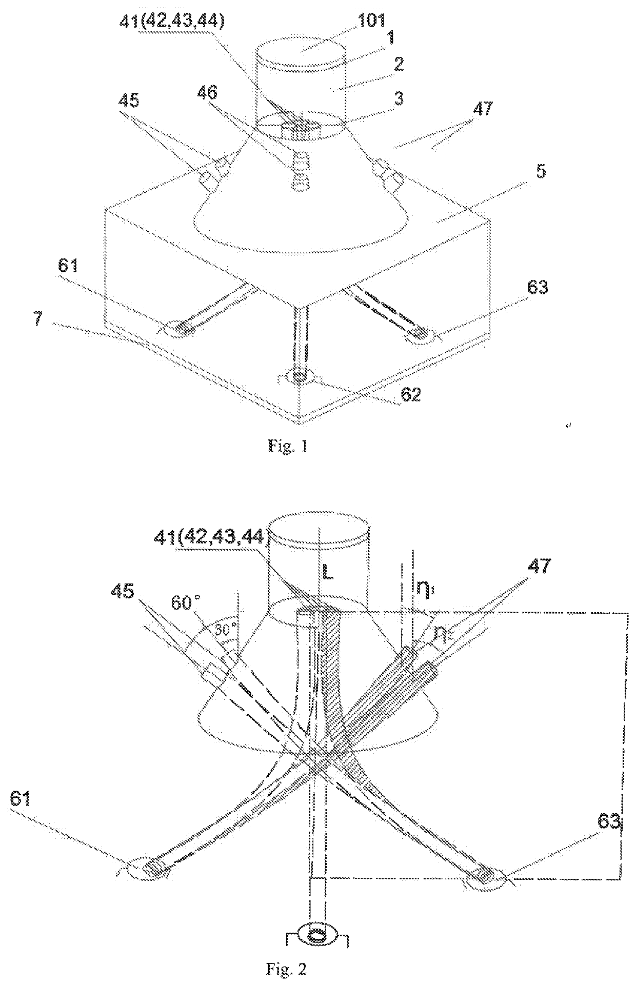
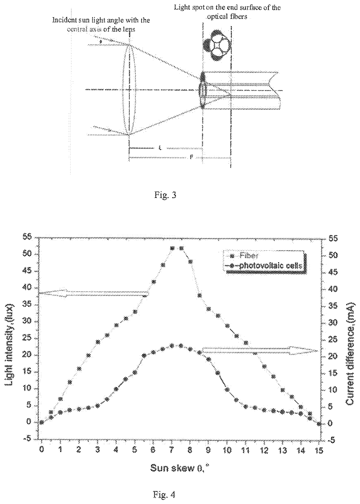
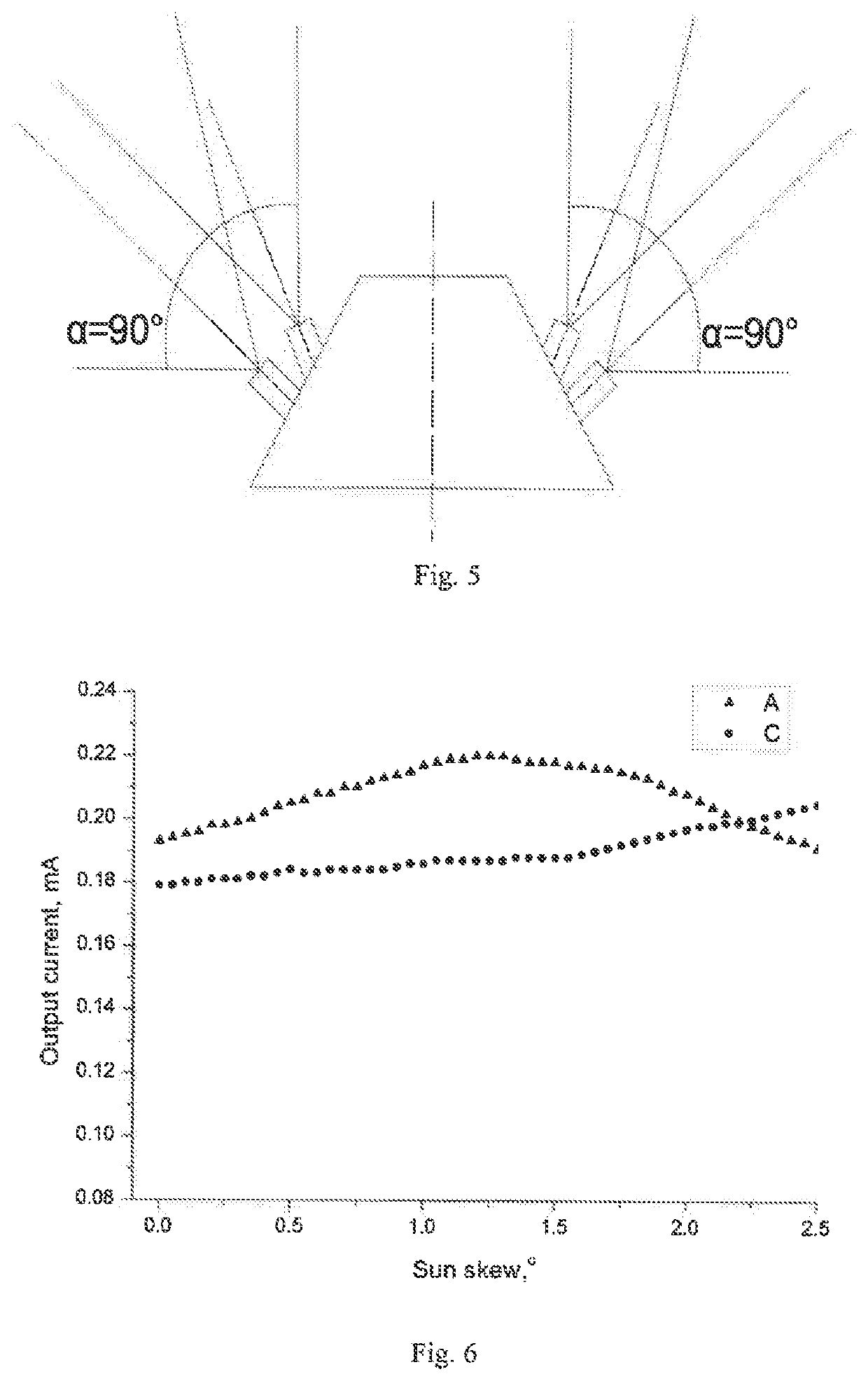
[0032]FIG. 1 shows the structural diagram of the solar tracking sensor based on optical fibers, wherein the system comprising a fine-positioning module, a coarse-positioning module, and a signal acquisition module, wherein the fine-positioning module comprising a convex lens 1, a lens tube 2, a fixing tube 3 and four fine-positioning optical fibers 41-44, wherein the lens tube 2 comprises the first lens tube and the second lens tube, wherein the first lens tube is a cylinder, wherein the second lens tube is a circular truncated cone, and the two ends of the second lens tube are connected to the first lens tube and the dark box 5, respectively. The convex lens 1 is installed at the top of the lens tube 2. In order to filter out the unwanted lights such as inflared light, an optical filter 101 may be installed on the top of the convex lens.

[0033]The input end faces of the four...


PUM


Abstract

A solar tracking sensor includes lens and four fibers respectively representing four directions installed in a lens barrel to serve as a fine-positioning daylighting module, and four groups of fibers installed on the side of the lens barrel to serve as a coarse-positioning daylighting module. A circuit board and four photocells are installed at the bottom of a cassette. Each photocell is connected to fine positioning fibers located in the same direction as the photocell, and is connected to coarse positioning fibers located in a direction diagonal to the direction of the photocell. By using a daylighting method of combining fine-positioning daylighting and coarse-positioning daylighting, the number of the photocells is reduced, the design of the circuit board is simplified, and costs are reduced; moreover, because the coarse-positioning daylighting module can collect sunlight in a wide-angle range, the tracking angle range of the sensor is enlarged.

Description

TECHNICAL FIELD[0001]The invention relates to a solar tracking sensor, especially a solar tracking sensor based on optical fibers.BACKGROUND ART[0002]With the continuous consumption of fossil energy, the development of renewable energy sources has become increasingly urgent. Among all renewable energy sources, solar energy has become one of the important energy sources because of its large quantity, clean and pollution-free characteristics. However, the solar energy also has the disadvantages of uneven distribution and intensity, which increase the difficult of the development and utilization of the solar energy.[0003]Researchers have conducted in-depth and extensive solar energy research, and solar energy products such as water heaters, solar photovoltaic power generation equipment have been successfully put into application, which saves energy and has brought great convenience to human life. However, these are all fixed position solar products. Compared with the moving sun of the ...

Claims


Application Information

Patent Timeline
IPC IPC(8): H02S20/32H02S40/20G05D3/10
CPCH02S20/32G05D3/105H02S40/20G01C1/00G05D3/12F24S50/20G02B6/06G02B6/4202G02B6/4249G02B6/4298Y02E10/47Y02E10/50
Inventor CHEN, MINGYANGZHANG, LILIU, PIPICAO, GUODONGXU, XIAOMING
Owner JIANGSU UNIV
Learn More