Reel device

a technology of a rope and a loop is applied in the field of rope devices, which can solve the problems of easy loosening of ropes, and achieve the effects of effective release or wrapping of ropes, simple structure and preventing rope loosening

Active Publication Date: 2020-03-19
WANG YU CHIEN
View PDF3 Cites 5 Cited by
  • Summary
  • Abstract
  • Description
  • Claims
  • Application Information

AI Technical Summary

Benefits of technology

[0005]The major object of the present invention is to provide a reel device, which can effectively release or wrap a rope with a simple structure and prevent the rope from getting loose.

Problems solved by technology

The sticky buckle member may be, for example, a Velcro, and easily loosened; therefore, the rope may be easily loosened, and the sticky buckle member is unable to buckle the rope firmly so that the rope will slide or fall off relative to the sticky buckle member and that the protective equipment cannot wrap around a human body part tightly and closely.

Method used


Image

  • Reel device
  • Reel device
  • Reel device

Examples


Embodiment Construction

[0017]The present invention will be clearer from the following description when viewed together with the accompanying drawings, which show, for purpose of illustrations only, the preferred embodiment in accordance with the present invention.

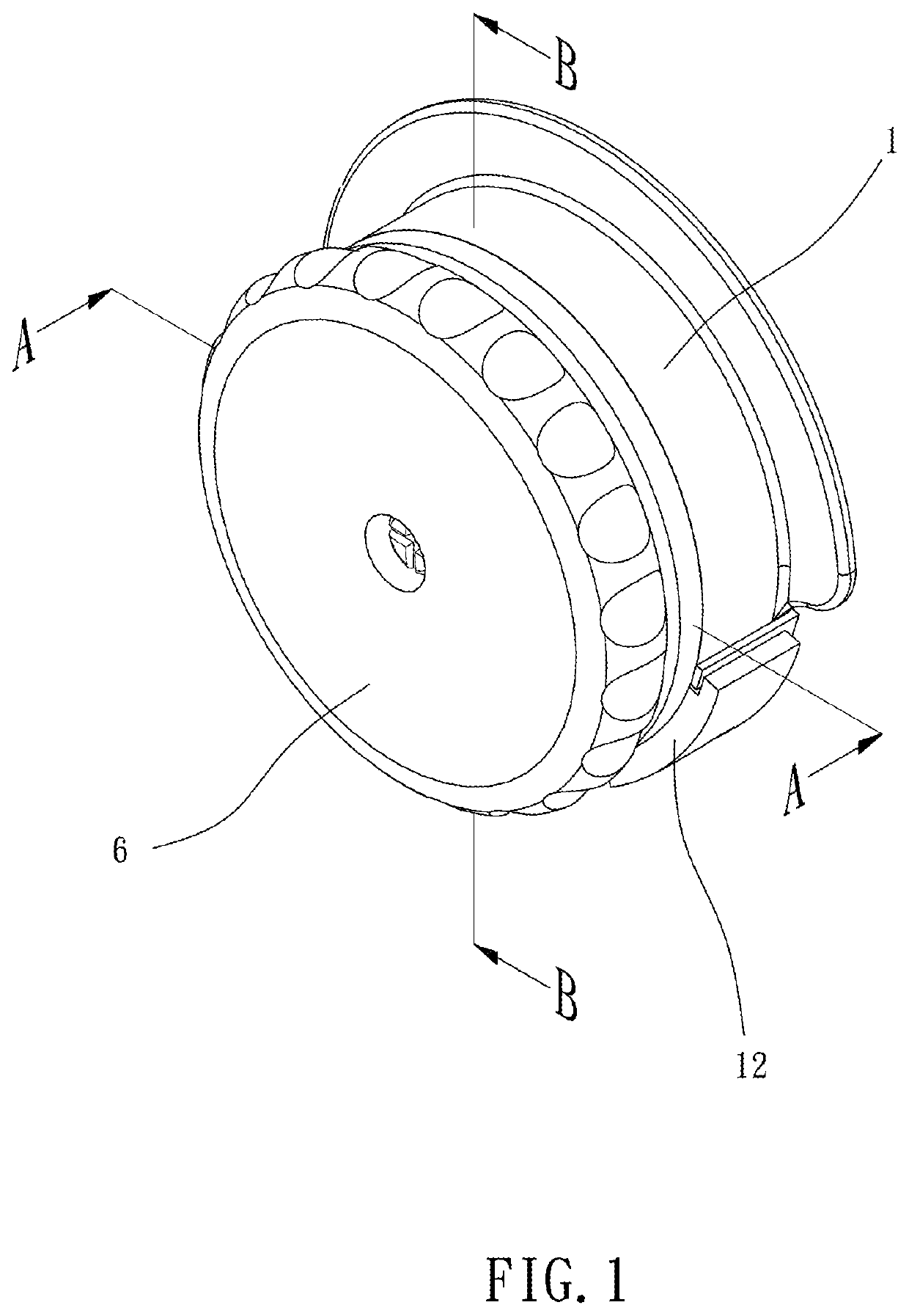
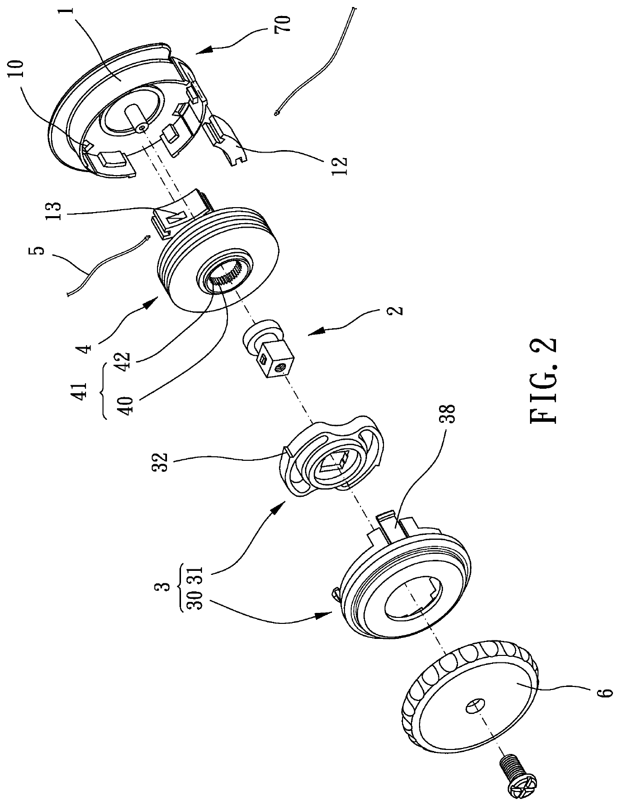
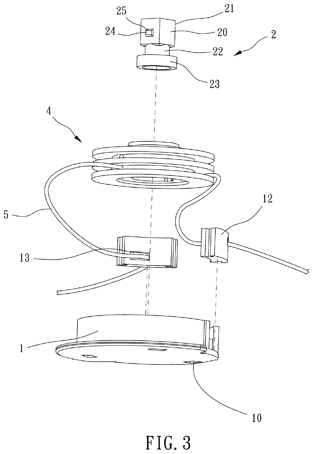
[0018]Please refer to FIGS. 1 to 9 for a preferred embodiment of the present invention. A reel device includes a shell body 1, a rotating shaft 2, a ratchet assembly 3 and a reel unit 4.

[0019]The rotating shaft 2 is movably along an axial direction L and rotatably disposed in the shell body 1, the rotating shaft 2 includes a head section 20, and an exterior circumferential face of the head section 20 circumferentially has a plurality of engaging teeth 21 circumferentially disposed thereon and extending radially; a ratchet assembly 3 includes a first ratchet portion 30 and a second ratchet portion 31 which is meshed with the first ratchet portion 30, the first ratchet portion 30 is fixed on the shell body 1, the second ratchet portion 31 is rotata...


PUM


Abstract

A reel device is provided, including a shell body; a rotating shaft, movably and rotatably disposed in the shell body along an axial direction, the rotating shaft including a head section, an exterior circumferential face of the head section circumferentially having a plurality of engaging teeth circumferentially disposed thereon and extending radially; a ratchet assembly, including a first ratchet portion and a second ratchet portion meshed with the first ratchet portion, the first ratchet portion being fixed on the shell body, the second ratchet portion being rotatable relative to the first ratchet portion unidirectionally, the second ratchet portion comovably connected with the rotating shaft; a reel unit, rotatably disposed on the shell body for being connected to at least one rope, the reel unit having a meshed hole extending in the axial direction, the plurality of engaging teeth being radially detachably engaged with the meshed hole.

Description

BACKGROUND OF THE INVENTIONField of the Invention[0001]The present invention relates to a reel device which is rotatable and foldable.Description of the Prior Art[0002]Generally, to meet a user's requirements, a common wearable equipment such as shoes and protective equipment has an adjustable structure for being adjusted to an appropriate tightness and height for the user. For example, a neck brace provides a height adjusting feature to adjust an upper edge height of the neck brace to support a front edge of the chin of the user so that the user can look forward at eye-level.[0003]However, this type of conventional reel device includes a sticky buckle member which is disposed through a wearable device, the sticky buckle member can positionably buckle the rope, and the user can pull the sticky buckle member to drive the rope to move up and down and positionably buckle the rope. The sticky buckle member may be, for example, a Velcro, and easily loosened; therefore, the rope may be ea...

Claims


Application Information

Patent Timeline
Patent Type & Authority Applications(United States)
IPC IPC(8): B65H75/44
CPCB65H75/4471B65H75/4465B65H75/4415B65H75/4492A43C11/165
Inventor WANG, YU-CHIEN
Owner WANG YU CHIEN
Why Eureka
Try Eureka