
A crop monitoring system and method

a crop and monitoring system technology, applied in soil-working methods, digger harvesters, agriculture tools and machines, etc., can solve the problems of difficult parameter determination, difficult to assess parameters of some crops before they are harvested, and large root vegetables

Active Publication Date: 2020-03-19
B HIVE INNOVATIONS LTD
View PDF3 Cites 25 Cited by
  • Summary
  • Abstract
  • Description
  • Claims
  • Application Information

AI Technical Summary

Benefits of technology

The present patent describes a harvester monitoring system that can determine various parameters associated with harvested items, such as their size and weight. The system includes a camera module that captures image data of the harvested items, a mounting bracket that securely attaches the camera module to the harvester, a location sub-system that identifies the geographical location of the monitoring system, and a processing unit that analyzes the image data and determines the parameters associated with the harvested items. The system can also include a protective case for the camera module, batteries to power the monitoring system, and a communication sub-system to transmit the parameters to a remote management system. The technical effects of the invention include improved monitoring of harvested items and improved efficiency in the agricultural process.

Problems solved by technology

The assessment of parameters associated with some crops before they are harvested is difficult.
In particular, it is difficult to determine parameters such as the size of such root vegetables before the root vegetables are harvested because they are underground.
This process is prone to errors, however.
In particular, the or each sample may not be representative of the larger area.
Mismatches between the expected and actual parameters can have consequences on the sale, management, handling, and storage of the root vegetables.
The same or similar issues arise in relation to other harvestable items, other than root vegetables.

Method used


Image

  • A crop monitoring system and method
  • A crop monitoring system and method
  • A crop monitoring system and method

Examples


Embodiment Construction

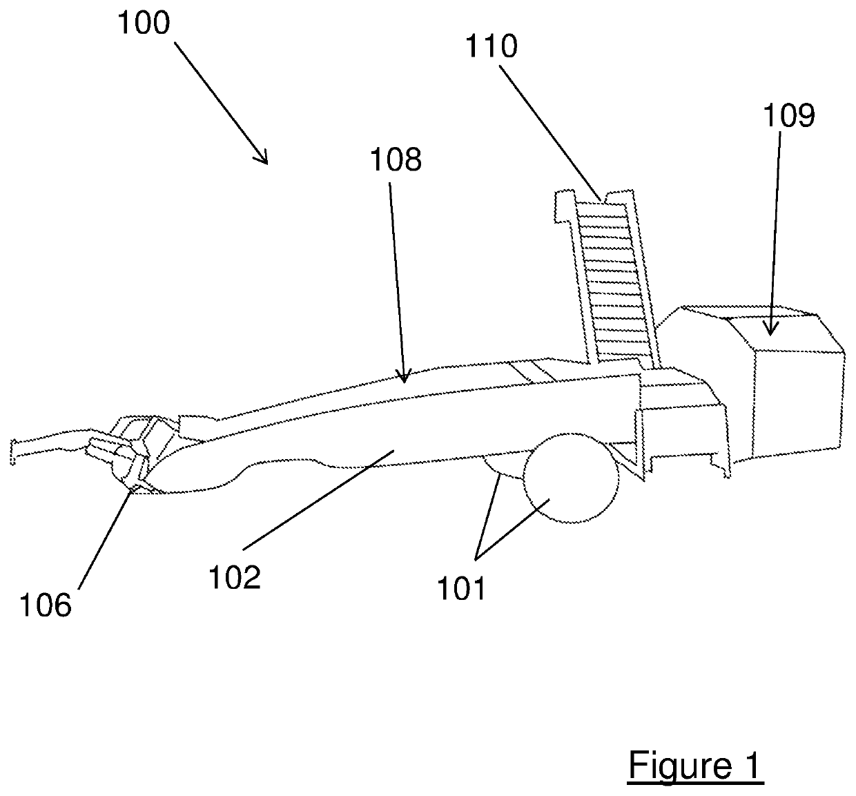
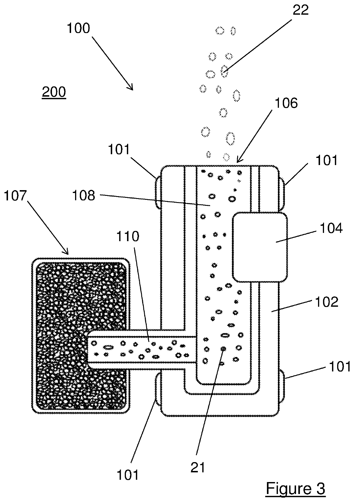
[0066]Embodiments may include a monitoring system 1 which is configured to determine one or more parameters associated with one or more harvested items 21.

[0067]The monitoring system 1 (see FIG. 6, for example) includes an imaging sub-system 11 which is configured to determine the one or more parameters. The monitoring system 1 may include one or more of: a storage sub-system 12, a communication sub-system 13, a location sub-system 14, and a power sub-system 15.

[0068]The location sub-system 14 may be configured to determine the current location of the monitoring system 1 (or a part thereof). This location may be a longitude and latitude, for example. In some embodiments, the location may be a location relative to a fixed geographical location.

[0069]The storage sub-system 12 may be configured to store the one or more parameters and / or the current location (as determined by the location sub-system 14, if provided). The storage sub-system 12 may be further configured to store other inf...


PUM


Abstract

A harvester monitoring system configured to determine one or more parameters associated with harvested items, the system comprising: a camera module having a field of view and configured to generate image data associated with the harvested items; a mounting bracket configured to secure the camera module to a harvester such that a conveyor of the harvester is within the field of view of the camera module; a location sub-system configured to determine and output location data representative of a geographical location of the harvester monitoring system; and a processing unit configured to receive the image data and the location data, to determine one or more parameters associated with the harvested items, and to record the one or more parameters in association with the location data on a computer readable medium.

Description

CROSS-REFERENCE TO RELATED APPLICATIONS[0001]This application claims priority to International Application No. PCT / GB2017 / 053789, filed on Dec. 18, 2017, entitled “A CROP MONITORING SYSTEM AND METHOD,” which claims the benefit of United Kingdom Patent Application GB 1621879.4, filed on Dec. 21, 2016, entitled “A CROP MONITORING SYSTEM AND METHOD,” and United Kingdom Patent Application GB 1713953.6, filed on Aug. 31, 2017, entitled “A CROP MONITORING SYSTEM AND METHOD,” the disclosures of which are all hereby incorporated herein by reference in their entirety.BACKGROUND[0002]Embodiments of the present disclosure relate to systems and methods for monitoring harvesters and crops. More specifically, some embodiments are directed to systems and methods for monitoring, at the harvesting stage, one or more parameters associated with one or more harvested items (such as root vegetables).[0003]The assessment of parameters associated with some crops before they are harvested is difficult. Thi...

Claims


Application Information

Patent Timeline
IPC IPC(8): A01D41/127A01D17/00A01D43/08A01D33/00A01D91/00
CPCA01D2033/005A01D17/00A01D91/00A01D41/127A01D33/00A01D43/087A01D91/02A01C21/007A01B79/005A01B47/00A01B69/001
Inventor GURURAJAN, VIDYANATHWRIGHT, ALISONHANSEN, MARKHALES, IANSMITH, MELVYNSMITH, LYNDONSAMWORTH, DAVEGREENWOOD, LUKE
Owner B HIVE INNOVATIONS LTD
Learn More