Securing device and method for operating a securing device

a technology of securing device and locking mechanism, which is applied in the direction of friction clutches, non-mechanical actuated clutches, manipulators, etc., can solve the problem of difficulty in fixing the manipulator arms with an engine brake, and achieve the effect of reducing the risk of tilting

Active Publication Date: 2020-03-05
M ROBOT OHG
View PDF0 Cites 0 Cited by
  • Summary
  • Abstract
  • Description
  • Claims
  • Application Information

AI Technical Summary

Benefits of technology

[0032]As a result, an at least almost homogeneous force distribution of the clamping force of the spring means can be achieved, whereby the risk of tilting is reduced when transferring the clamping unit from the release position into the clamping position.
[0033]Moreover, in one embodiment of the securing device, it proves to be

Problems solved by technology

Such manipulators work mostly gearless, which makes it di

Method used


Image

  • Securing device and method for operating a securing device
  • Securing device and method for operating a securing device

Examples


Embodiment Construction

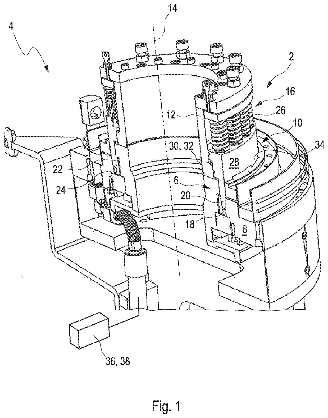
[0044]FIG. 1 shows a securing device for a rotatably mounted object 4, which is generally designated by the reference numeral 2. The object 4 may be a manipulator, for example a direct drive.

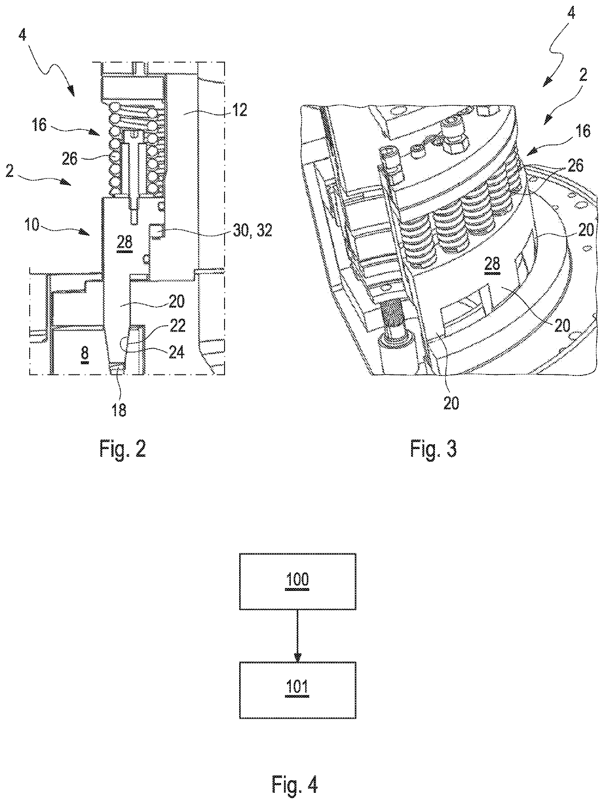
[0045]The securing device 2 comprises a receiving unit 6, which is fixed against rotation on a first component 8 of the object 4. In addition, the securing device 2 comprises a clamping unit 10, which is fixed to a second component 12 of the object 4. The second component 12 is moveable manually or by means of a rotary drive, in particular direct drive, relative to the first component 8 via a rotatably mounted joint about a rotational and / or swivel axis 14.

[0046]In addition, the securing device 2 comprises a drive unit 16, in the clamping unit 10 in a release position in which the first component 8 and the second component 12 are released for rotation relative to each other, which can be transferred parallel to the rotational and / or swivel axis 14 in a clamping position, in which the clamping un...


PUM


Abstract

A securing device for a rotatably mounted object with at least one receiving unit, which is fixed against rotation on a first component of the object with at least one clamping unit which is fixed against rotation to a second component of the object, which manually or by means of a rotary drive is moveable relative to the first component via a rotatably mounted joint about a rotational and/or swivel axis, and with at least one drive unit through which the clamping unit can be transferred from a release position, in which the first component and the second component are released for rotation relative to each other to a clamping position, in which the clamping unit frictionally and/or non-positively engages in the receiving unit, and the first component and the second component are fixed relative to each other against rotation about the rotary and/or swivel axis.

Description

CROSS REFERENCE TO RELATED APPLICATIONS[0001]This application claims priority to Germany application DE 10 2018 121 701.3, filed Sep. 5, 2018, which is incorporated by reference in its entirety.FIELD OF THE INVENTION[0002]The invention relates to a securing device and a method for operating a securing device.BACKGROUND OF THE INVENTION[0003]There are securing devices for manipulators, such as industrial robots, known in which the manipulators are controlled by mechanical transmission.[0004]The components include, for example, manipulator arms or robotic arms. When the mechanical drives are at a standstill, the gearboxes fix the robot arms at a standstill relative to one another.[0005]In addition, securing devices for components are known in which additional brakes are provided, which, similar to a disc brake surface, fix the components relative to each other by means of static friction.[0006]In addition, manipulators are known with direct drive, thus manipulators in which the indivi...

Claims


Application Information

Patent Timeline
IPC IPC(8): B25J9/00B25J9/12
CPCB25J9/126B25J9/0009B25J15/0052B25J19/06B25J19/0004F16D25/0632F16D13/36
Inventor BARTSCH, PATRICKBRISSE, DIRK
Owner M ROBOT OHG
Why Eureka
Try Eureka