
Specular component estimation in a wireless communication network

Active Publication Date: 2020-02-20
KONINKLJIJKE PHILIPS NV
View PDF0 Cites 3 Cited by
  • Summary
  • Abstract
  • Description
  • Claims
  • Application Information

AI Technical Summary

Benefits of technology

The described embodiments in this patent text are advantageous because they don't require identifying the desired communication direction or the most dominant multi-path components based on an estimation of the radio channel using the received frequency / time domain signals. Instead, the communication direction or path components in the radio channel are determined based on the characteristics of the subcarrier-beamformer at the transmitter. This simplifies the determination process and avoids complex calculations for estimating the radio channel.

Problems solved by technology

However, this involves estimating the frequency / time domain signals which may not be accurate enough and may include substantial calculating overhead.

Method used


Image

  • Specular component estimation in a wireless communication network
  • Specular component estimation in a wireless communication network
  • Specular component estimation in a wireless communication network

Examples


Embodiment Construction

[0038]In the following, embodiments of the present invention are described in further detail with reference to the enclosed drawings in which elements having the same or similar function are referenced by the same reference signs.

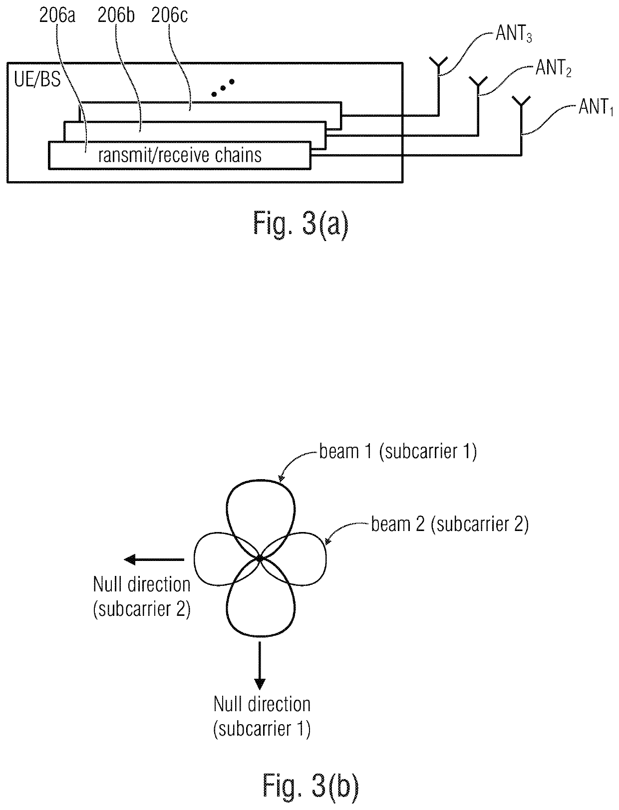
[0039]Embodiments of the inventive approach will now be described. A multi-carrier signal provided by a UE with a spatial coding may be used for the estimation of specular components useful for a reliable communication in an uplink (UL) communication between the UE and the BS.

[0040]FIG. 3(a) shows a schematic representation of a UE including a plurality of antennas ANT1 to ANT5 and a plurality of transmit / receive chains 206a to 206c. The BS may have a similar structure. The UE having the two or more than two antenna ports and the at least two transmit / receive chains 206a to 206c may select a set of two antennas, for example antennas ANT1 and ANT2, having a sufficient antenna spacing, for example an antenna spacing being below 0.8 lambda to ensure a single N...


PUM


Abstract

An apparatus includes an antenna array having a plurality of antennas. The antenna array is configured to receive a multi-carrier signal from a multi-antenna transmitter over a radio channel. The multi-carrier signal has at least two subcarriers, and each subcarrier is mapped at the transmitter to a respective subcarrier-beamformer. The respective subcarrier-beamformers has non-identical null and beam cone directions. A processor is configured to identify a communication direction for a radio signal communication between the apparatus and the transmitter. The communication direction is identified based on one or more specular path components of the radio channel which are related to a null or to a maximum of a subcarrier-beamformer.

Description

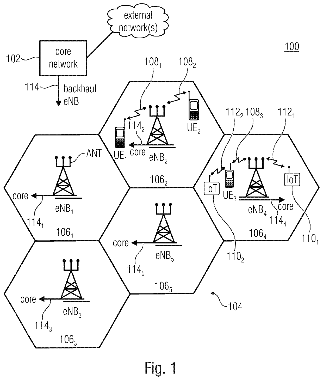
CROSS-REFERENCES TO RELATED APPLICATIONS[0001]This application is a continuation of copending International Application No. PCT / EP2018 / 060381, filed Apr. 23, 2018, which is incorporated herein by reference in its entirety, and additionally claims priority from European Application No. EP 17 168 791.6, filed Apr. 28, 2017, which is incorporated herein by reference in its entirety.BACKGROUND OF THE INVENTION[0002]The present invention relates to the field of mobile communication networks and, more specifically, to approaches allowing for a reliable communication between respective entities of a mobile communication network, for example a reliable communication between a base station and a mobile device or another user equipment (UE) of the mobile communication network, or between a plurality of base stations of the mobile communication network, or between a plurality of mobile devices of the mobile communication network.[0003]FIG. 1 is a schematic representation of an example of a wir...

Claims


Application Information

Patent Timeline
IPC IPC(8): H04B7/08H04B7/06H04L27/26
CPCH04B7/0617H04L27/2628H04B7/0897H04B7/086H04L27/2636H04L27/2634H04B7/0456H04B7/0413H04B7/0404H04B7/0671
Inventor HAUSTEIN, THOMASTHIELE, LARSKEUSGEN, WILHELMGROSSMANN, MARCUSLANDMANN, MARKUS
Owner KONINKLJIJKE PHILIPS NV
Learn More