
Vehicle interior member

a technology for interior members and vehicles, applied in vehicle components, superstructure subunits, transportation and packaging, etc., can solve the problems of ribs not reaching ribs may not be able to meet the intended travel distance, and ribs may be caught between the vehicle body member and the interior member

Active Publication Date: 2020-02-20
KASAI KOGYO CO LTD
View PDF0 Cites 0 Cited by
  • Summary
  • Abstract
  • Description
  • Claims
  • Application Information

AI Technical Summary

Benefits of technology

The present invention aims to provide a vehicle interior member that can effectively absorb the input energy of a load. This is important because there are concerns that the reduction in distance between a vehicle body member and an interior component covering it may lead to a reduction in stiffness of the vehicle body, which may affect the absorption of input energy. The invention proposes to address this issue by designing a vehicle interior member that can properly absorb the input energy of a load, thereby ensuring safety and comfort for the vehicle occupants.

Problems solved by technology

Accordingly, it is often difficult to design the conventional shock absorbing structure with an enough travel distance for the rib to collapse.
In a case where the collapsed rib is caught between the vehicle body member and the interior member, the rib may fail to reach the intended travel distance.
Similarly, with the conventional structure including the rib to be torn also, the torn rib may be caught between the vehicle body member and the interior member, failing to fully travel.

Method used


Image

  • Vehicle interior member
  • Vehicle interior member
  • Vehicle interior member

Examples


Embodiment Construction

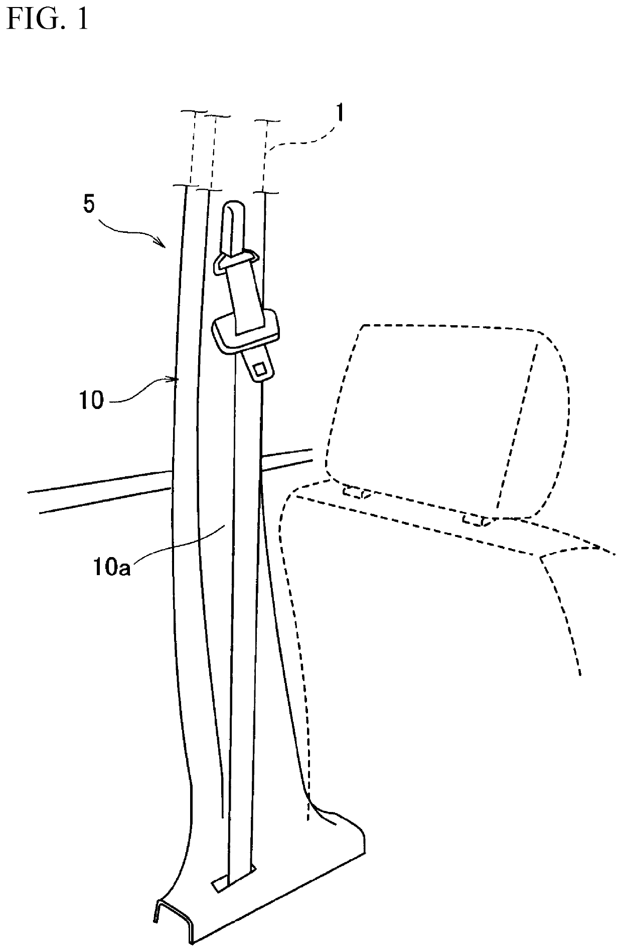
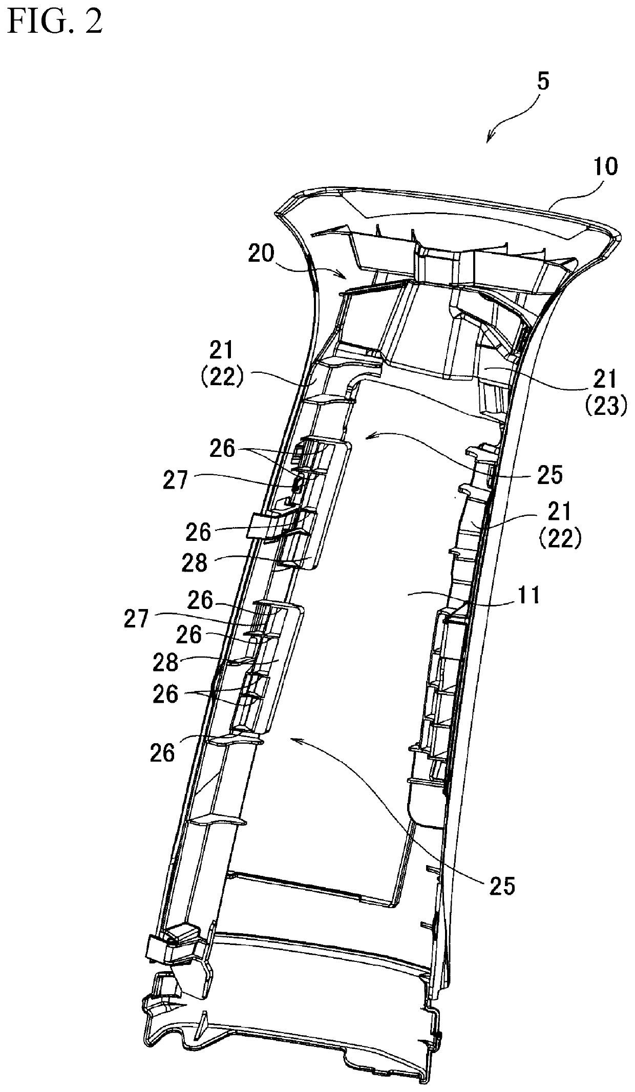
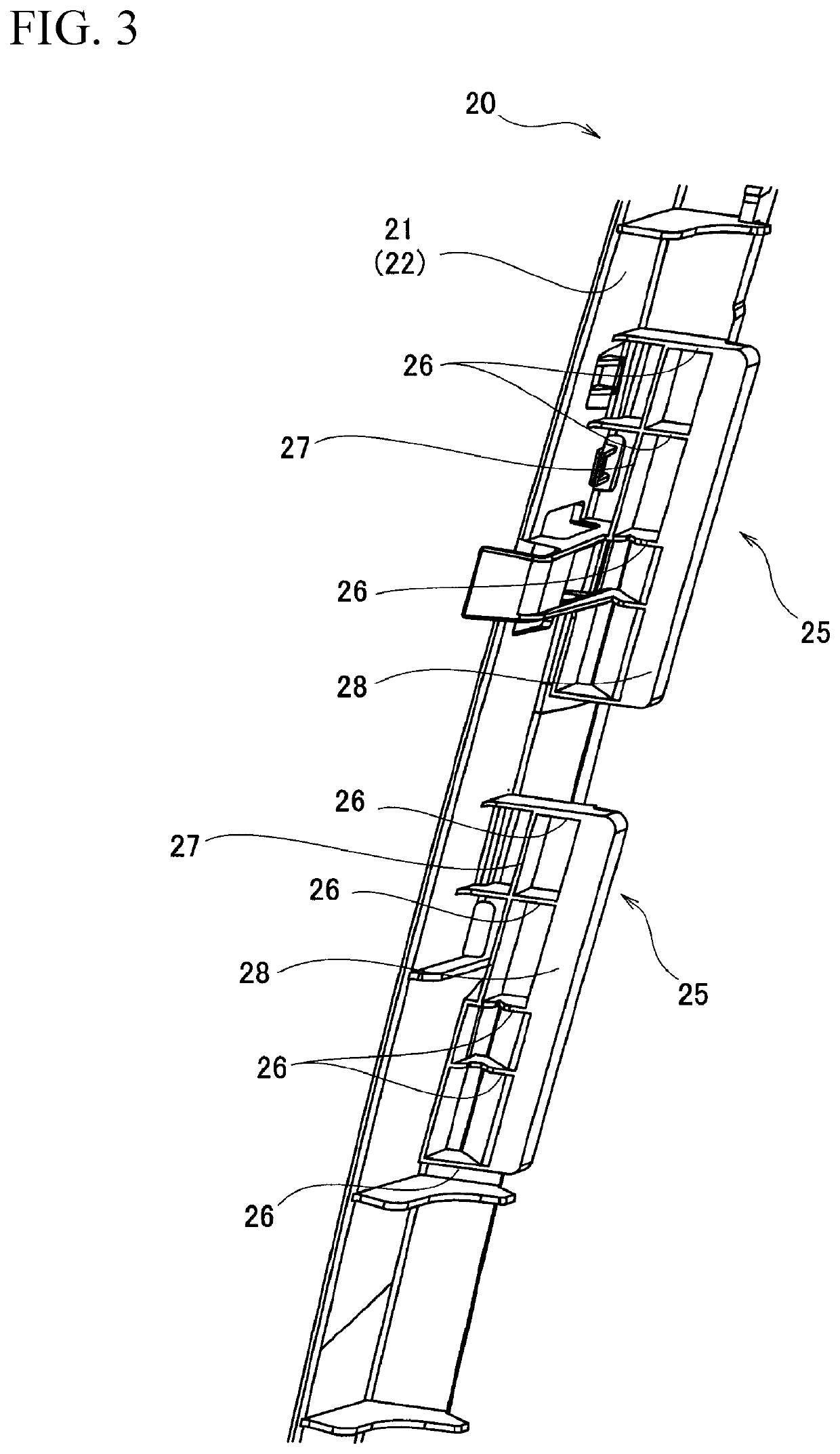
[0019]In the following, a description will be given of a center pillar 1 which is a vehicle body member of an automobile, as a vehicle interior member according to the present embodiment. FIG. 1 is a schematic perspective view of a center pillar trim 5 which covers the center pillar 1 on the cabin side. FIG. 2 is a schematic perspective view of the back surface side of the center pillar trim 5. FIG. 3 is a perspective view of a main part of an absorbing member 20 mainly formed of an absorber 25. FIG. 4 is an explanatory cross-sectional view of the center pillar 1 including the center pillar trim 5.

[0020]The center pillar 1 forms a top-bottom direction frame member across a vehicle body opening where a side door is to be mounted. The bottom end of the center pillar 1 is coupled to a vehicle side sill (not shown) which forms a front-rear direction frame member on the floor side.

[0021]The center pillar 1 includes a panel 2 on the cabin side, which panel 2 includes a bead-shaped part 2a...


PUM


Abstract

A vehicle interior member which absorbs input energy of a load properly is provided. A center pillar trim includes a trim body configured to cover a center pillar, and an absorber provided between the trim body and the center pillar. The absorber includes: a plurality of horizontal ribs rising perpendicularly to a face of the trim body having their respective faces opposed to each other; a contact surface provided continuously across the plurality of ribs so as to oppose to a bead-shaped part, which is provided at the center pillar to partially bulge on the cabin side.

Description

CROSS-REFERENCE TO RELATED APPLICATIONS[0001]This application is a National Stage Entry application of PCT International Application No. PCT / JP2017 / 019993, filed on May 30, 2017, the entire contents of which are hereby incorporated by reference.BACKGROUND1. Technical Field[0002]The present invention relates to a vehicle interior member.2. Description of the Background[0003]Conventionally, the cabin of a vehicle is furnished with an interior member which covers a body member of the vehicle for any decorative or functional purposes. One known interior member of this kind includes a shock absorbing structure intended to address a load applied to the interior member on the cabin side.[0004]For example, Japanese Unexamined Patent Application No. 11-208396 discloses a shock absorber formed of a rib structure fitted into the back surface of a garnish body. Japanese Unexamined Patent Application No. 10-152005 discloses a rib structure which absorbs energy by a rib being torn.BRIEF SUMMARY[0...

Claims


Application Information

Patent Timeline
IPC IPC(8): B60R13/02
CPCB60R13/025B60R13/0206
Inventor ISOSAKI, YASUHIKO
Owner KASAI KOGYO CO LTD
Learn More