Pneumatic tire

a technology of pneumatic tires and tyres, which is applied in the field of pneumatic tires, can solve the problems of reducing the strength affecting the performance of the bead core, and the rupture so as to improve the fatigue resistance of the carbon fibers, reduce the weight of the bead core, and improve the strength

Active Publication Date: 2020-01-30
YOKOHAMA RUBBER CO LTD
View PDF0 Cites 3 Cited by
  • Summary
  • Abstract
  • Description
  • Claims
  • Application Information

AI Technical Summary

Benefits of technology

The present invention involves a bead core for a pneumatic tire that includes a composite cord made of carbon fibers and glass fibers. By using this composite cord, the bead core has improved fatigue resistance and can withstand higher stresses. Additionally, the bead core has a reduced weight and can be easily reduced in size. The composite cord is spirally wound around an annular core body, which ensures uniform tension and prevents concentration of stress on the cord. The carbon fibers in the composite cord are between 20% to 80% of the total cross-sectional area, ensuring optimal strength and fatigue resistance. The core body can be made of metal or non-metal materials, depending on the desired weight reduction. The siding wires in the composite cord are covered with a film that improves adhesiveness to rubber, making the bead core more durable.

Problems solved by technology

The buckling may reduce the strength of the bead cores, leading to rupture of the bead cores.
Additionally, even in a case where the wire of the bead cores has a sufficient strength, the bead cores may be broken due to stress concentration in a case where the elongation of the bead cores at break is small.
Thus, it is presently difficult to put, to practical use, a pneumatic tire in which a wire formed of a material other than metal is used for the bead cores.
However, these documents do not suggest that the rubber reinforcing cords as described above be applied to the specific members of the bead cores, and the documents teach no specific requirements for application to the bead cores.

Method used


Image

  • Pneumatic tire
  • Pneumatic tire
  • Pneumatic tire

Examples


example

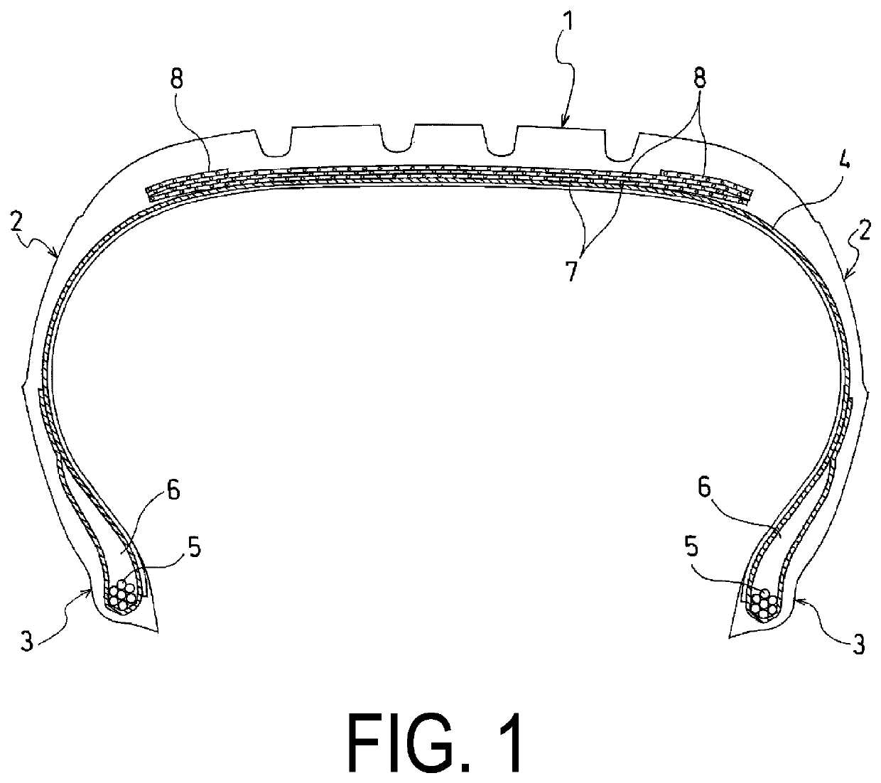
[0053]Tires according to Conventional Example 1, Comparative Examples 1 and 2, and Examples 1 to 3 were manufactured. The tires are pneumatic tires having the same configuration including annular bead cores embedded in bead portions and a carcass layer locked on the bead cores, except for the structure of the bead cores, the tires each having a tire size of 205 / 55R16.

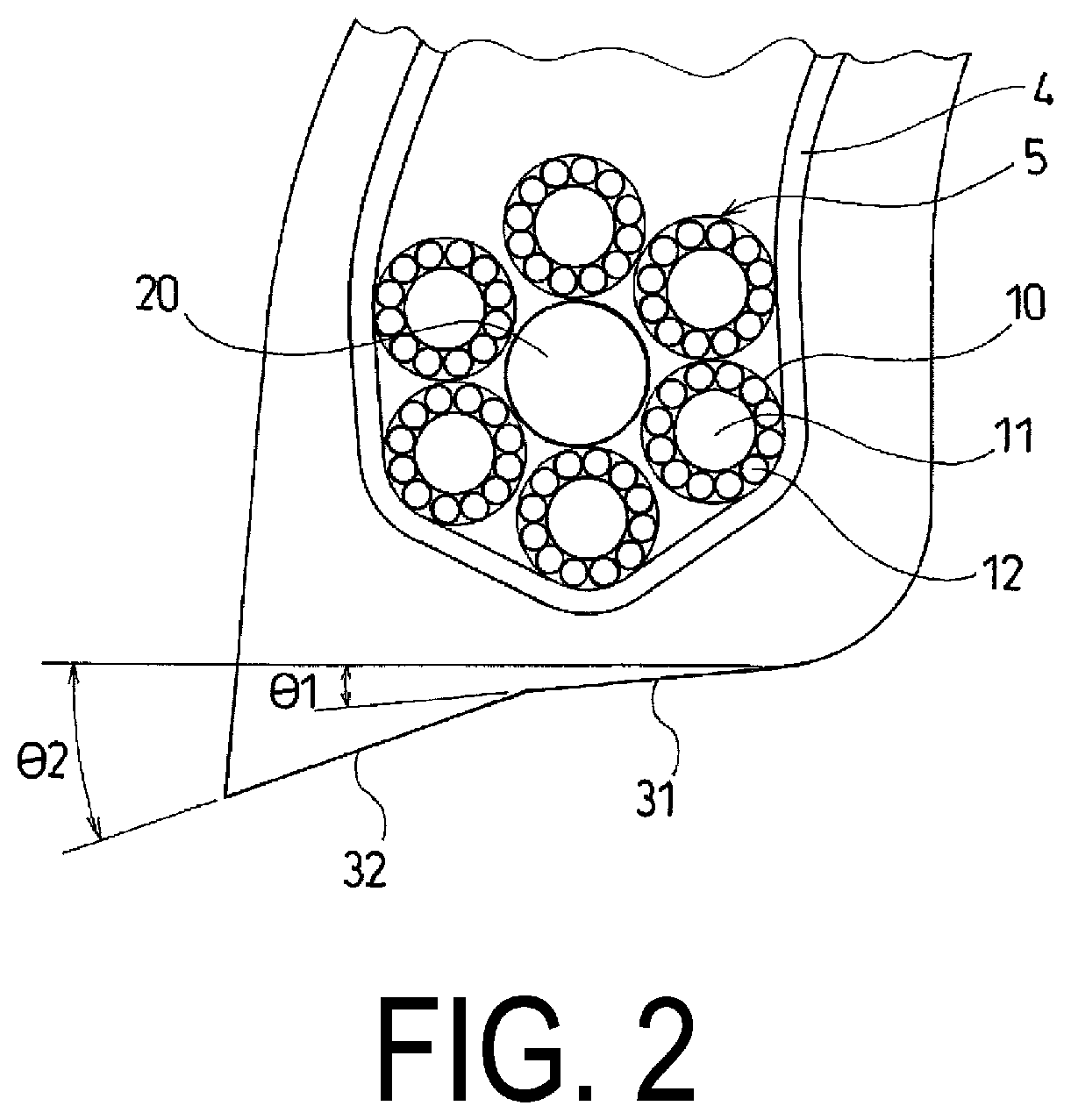
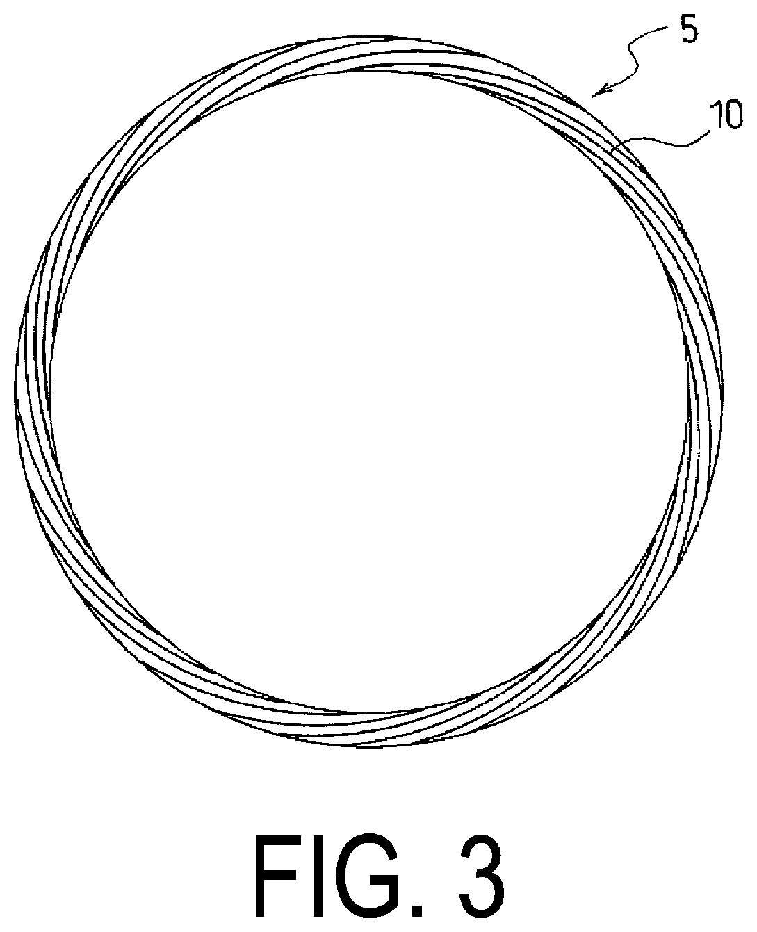
[0054]In Conventional Example 1, bead cores having a multilayer bead structure with a hexagonal cross section are employed, and steel wires are used for the bead cores. In Comparative Example 1, bead cores having a multilayer bead structure with a hexagonal cross section are employed, and as wires for the bead cores, composite cords are used that include a core wire formed of carbon fibers and a plurality of siding wires formed of glass fibers disposed around the core wire. In Comparative Example 2, bead cores having a cable bead structure are employed, and as wires for a core body and a side portion of each bead core, ...


PUM

PropertyMeasurementUnit
melting pointaaaaaaaaaa
tensile elastic modulusaaaaaaaaaa
diameteraaaaaaaaaa

Abstract

A pneumatic tire is provided that can achieve performance that is equivalent to or higher than that of known tires while allowing weight reduction of bead cores by using, for the bead cores, a composite cord. A pneumatic tire includes annular bead cores (5) embedded in bead portions (3), and a carcass layer (4) locked on the bead cores (5). Each of the bead cores (5) includes a cable bead structure in which a composite cord (10) is spirally wound around an annular core body (20), the composite cord including a core wire (11) formed of carbon fibers and a plurality of siding wires (12) formed of glass fibers disposed around the core wire (11).

Description

TECHNICAL FIELD[0001]The present invention relates to a pneumatic tire including annular bead cores embedded in bead portions and a carcass layer locked on the bead cores and more specifically relates to a pneumatic tire capable of achieving performance that is equivalent to or higher than that of known tires while allowing weight reduction of the bead cores by using, for the bead cores, a composite cord formed of a material other than metal.BACKGROUND ART[0002]Pneumatic tires generally include a carcass layer mounted between a pair of bead portions. Annular bead cores are embedded in the respective bead portions, and the carcass layer is turned up around the bead cores from a tire inner side to a tire outer side and locked on the bead cores.[0003]In the related art, as the bead cores of the pneumatic tire, multilayer beads are used that are formed by continuously and lamellarly winding one or more steel wires along the tire circumferential direction or cable beads are used that are...

Claims


Application Information

Patent Timeline
Patent Type & Authority Applications(United States)
IPC IPC(8): B60C15/05
CPCB60C2015/046B60C15/05B60C15/04B60C2015/042D07B1/0613D07B2501/2053D02G3/48D07B2205/306D07B2201/2059D10B2101/06D10B2101/12D07B2801/14D07B2801/24B60C15/024
Inventor HARIKAE, SHINYA
Owner YOKOHAMA RUBBER CO LTD
Why Eureka
Try Eureka