Photocatalytic Device

Inactive Publication Date: 2019-12-19
FLUX PHOTON CORP
View PDF7 Cites 3 Cited by
  • Summary
  • Abstract
  • Description
  • Claims
  • Application Information

AI Technical Summary

Benefits of technology

The present invention is a photocatalytic device that separates electron-hole pairs created by light absorption, similar to a photovoltaic device. The separated charges carriers, electrons and holes, interact with gas molecules to improve the specificity of desired reactions while minimizing unwanted back reactions. The device includes a p-type semiconductor and an n-type semiconductor connected to an electrical ground, allowing for independent interaction with molecules. It also includes high-surface area architectures, such as nanowires, nanotubes, and nanorods, to enable greater interaction with adsorbed or adjacent molecules. Overall, the device improves photocatalyst stability and simultaneously increases efficiency of desired reactions.

Problems solved by technology

Despite almost fifty years of research on the photocatalytic reduction of CO2, or water photoelectrolysis to cite another photocatalysis-based example, the scientific community is still a long way from efficient and commercially viable devices.
However while charge separation is promoted by the use of co-catalysts it remains imperfect, and ultimately the presence of both electrons and holes leads to deactivation of the co-catalysts.
However in application to photocatalytic reduction of CO2 it was found that the TiO2-generated holes were as ready to oxidize the CZTS as they were adsorbed gas molecules, a drawback since in realizing a practical system photocatalyst stability is of utmost importance. FIGS. 3A and 3B are schematic diagrams of a conventional photocatalytic device including metal contacts.

Method used


Image

  • Photocatalytic Device
  • Photocatalytic Device
  • Photocatalytic Device

Examples


Embodiment Construction

[0032]Reference will now be made in greater detail to a preferred embodiment of the invention, an example of which is illustrated in the accompanying drawings. Wherever possible, the same reference numerals will be used throughout the drawings and the description to refer to the same or like parts.

[0033]Having summarized the invention, the invention may be further understood by reference to the following detailed description and non-limiting examples.

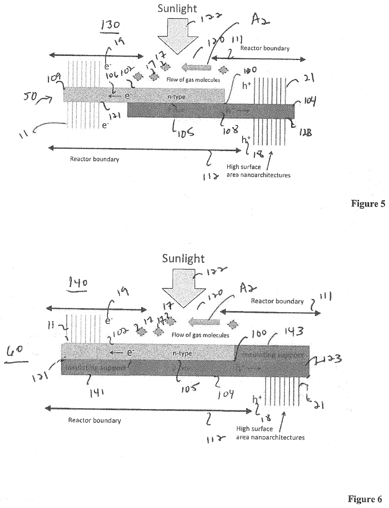
[0034]FIG. 4 is a schematic diagram of photocatalytic device 10. A pn-junction 100 is formed, to which there is spatial extent of n-type region 102 and p-type region 104 that are not in contact with the other. Electrons 19 generated in space-charge region 105 of pn-junction 100 are, due to the built-in electric field inherent in pn-junctions, swept into n-type material 106 of n-type region 102, while holes 18 are, for the same reason, swept into p-type material 108 of p-type region 104.

[0035]Holes 18 are free to travel along the length ...


PUM

PropertyMeasurementUnit
Lengthaaaaaaaaaa
Lengthaaaaaaaaaa
Wavelengthaaaaaaaaaa

Abstract

An improved photocatalytic device in which within semiconductors, absorbed electromagnetic radiation is known to generate electron-hole pairs; unwanted recombination of the radiation-generated electrons and holes is a significant limitation of photocatalytic efficiency, while the simultaneous local presence of both electrons and holes at the photocatalyst surface make reaction-specificity difficult to control. A photocatalytic device is described in which radiation-generated electrons and holes are spatially separated to be individually introduced into the reactant flow, minimizing unwanted recombination while promoting reaction-specific outcomes.

Description

FIELD OF THE INVENTION[0001]The present invention relates to an improved photocatalytic architecture that provides a means for spatially separating radiation-generated electrons and holes, minimizing unwanted electron-hole recombination, that simultaneously improves specificity of desired photocatalytic reactions while minimizing unwanted back reactions.BACKGROUND OF THE INVENTION[0002]The current annual global energy consumption roughly corresponds to the energy of the solar light reaching Earth in one hour; using this sunlight to make chemical fuels through photocatalysis offers a viable, and sustainable way to provide needed energy. Recycling of carbon dioxide via conversion into high energy-content fuel suitable for use in the existing hydrocarbon-based energy infrastructure is an intriguing concept for achieving sustainable solar fuels and reducing atmospheric CO2 concentrations, however this concept is realistically practical only if renewable energy sources are used for the t...

Claims


Application Information

Patent Timeline
IPC IPC(8): B01J19/12B01J35/00
CPCB01J35/0033B01J2219/1203B01J19/122B01J2219/0892B01J35/004B01J2219/0875B01J19/127B01J19/12B01J2219/0877B01J35/39B01J35/23B01J35/33
Inventor GRIMES, CRAIG A.KREISLER, KEVIN
Owner FLUX PHOTON CORP
Why Eureka
Try Eureka