
Deposition mask device and method of manufacturing deposition mask device

a mask and deposition mask technology, applied in the direction of electroluminescent light sources, vacuum evaporation coatings, coatings, etc., can solve the problems of reducing the luminous efficiency of the organic el display device, reducing the dimensional accuracy and position accuracy of the pixels, and unstable vapor deposition in the vicinity of the wall face of the through hole of the vapor deposition mask. , to achieve the effect of suppressing the occurrence of wrinkles and deformation

Active Publication Date: 2019-12-12
DAI NIPPON PRINTING CO LTD
View PDF0 Cites 8 Cited by
  • Summary
  • Abstract
  • Description
  • Claims
  • Application Information

AI Technical Summary

Benefits of technology

The patent text describes a vapor deposition mask device and a way to make it that prevents wrinkles and deformation during use. This improves the quality of the mask and the method of manufacturing it.

Problems solved by technology

That is, it is conceivable that the vapor deposition in the vicinity of the wall face of the through hole of the vapor deposition mask is unstable.
Therefore, when a vapor deposition mask is used to form the pixels of the organic EL display device, dimensional accuracy and positional accuracy of the pixels will be degraded.
As a result, the luminous efficiency of the organic EL display device is reduced.
However, it was found that the tension applied to the thinned vapor deposition mask causes the vapor deposition mask to be wrinkled or deformed.
In this case, when peeling off the metal layer from the substrate, the tension applied to the metal layer locally causes high stress, which may cause wrinkles or deformation in the peeled vapor deposition mask.

Method used


Image

  • Deposition mask device and method of manufacturing deposition mask device
  • Deposition mask device and method of manufacturing deposition mask device
  • Deposition mask device and method of manufacturing deposition mask device

Examples


Embodiment Construction

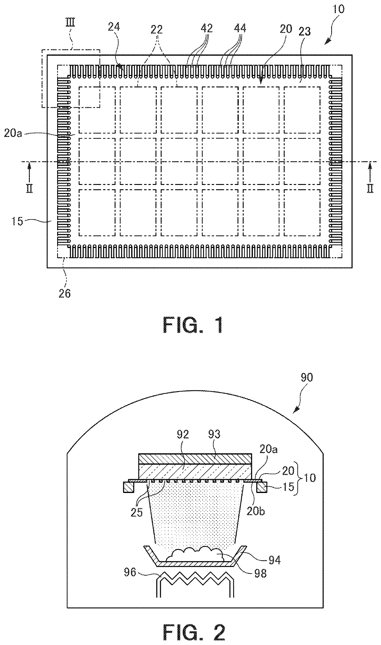
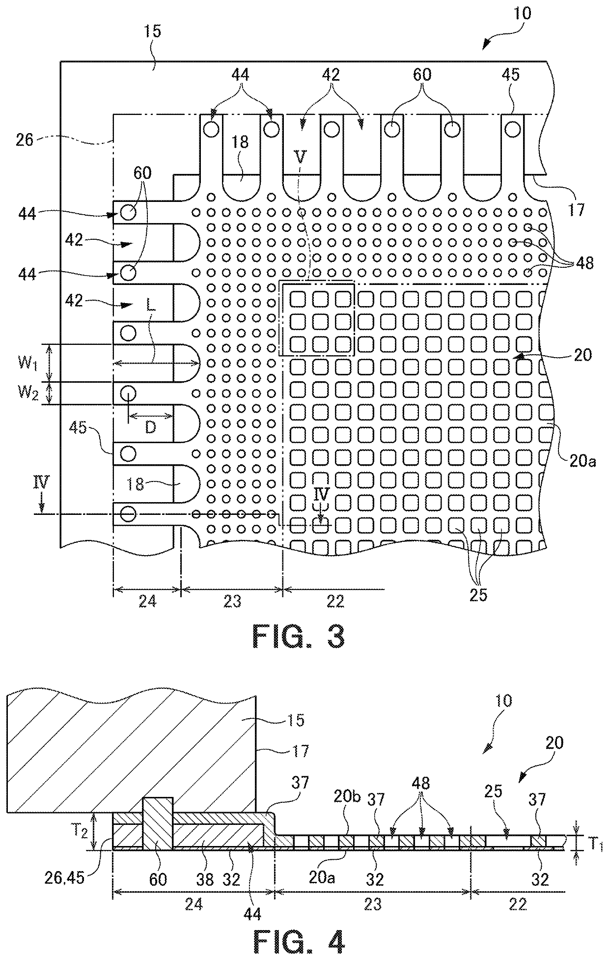
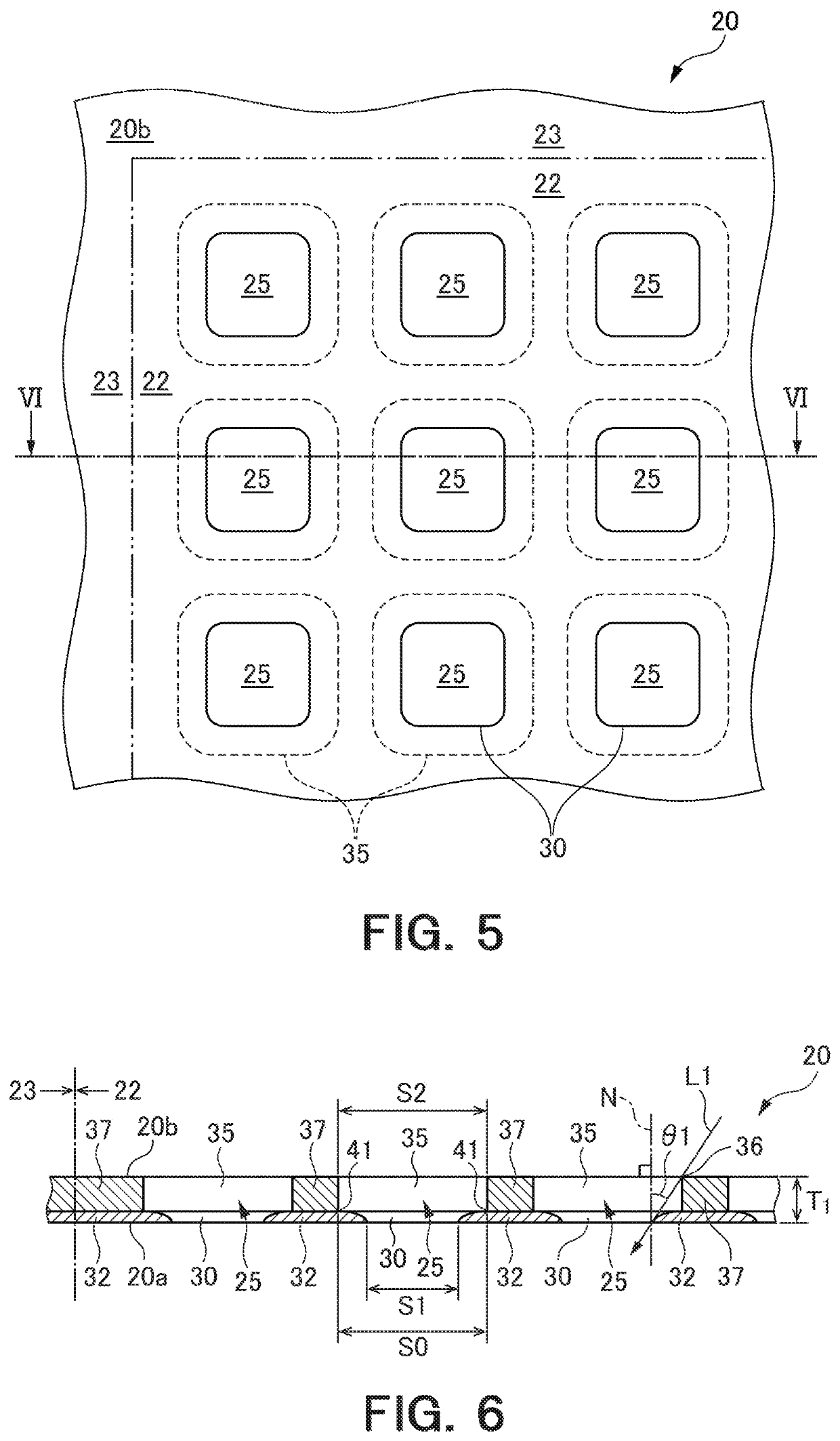
[0061]Hereinafter, an embodiment of the present disclosure will be described with reference to the drawings. In the drawings attached to the present specification, for convenience of ease of understanding and ease of illustration, scale ratios, longitudinal and lateral dimensional ratios and the like are exaggerated by changing from the actual ones.

[0062]FIGS. 1 to 46 are diagrams for explaining an embodiment according to the present disclosure. In the following embodiment, a vapor deposition mask device used to pattern an organic material on a substrate in a desired pattern when manufacturing an organic EL display device and a method of manufacturing the vapor deposition mask device will be described as an example. However, without being limited to such an application, the present disclosure can be applied to a vapor deposition mask device used for various applications and a method of manufacturing the vapor deposition mask device.

[0063]In the present specification, the terms “plat...


PUM

PropertyMeasurementUnit
thickness T1aaaaaaaaaa
width W1aaaaaaaaaa

Abstract

A vapor deposition mask device includes a vapor deposition mask having an effective region in which a plurality of first through holes is disposed, and a frame attached to the vapor deposition mask. The vapor deposition mask device includes a plurality of joint portions that joins the vapor deposition mask and the frame to each other. The plurality of joint portions is arranged along the outer edge of the vapor deposition mask. A notch is formed at a position corresponding to between two adjacent joint portions in the outer edge of the vapor deposition mask.

Description

CROSS-REFERENCE TO RELATED APPLICATIONS[0001]The present application is a continuation application of International Application No. PCT / JP2017 / 042297 filed on 24 Nov. 2017, which claims priority to Japanese Patent Application No. 2016-242400 filed on 14 Dec. 2016 and Japanese Patent Application No. 2017-222064 filed on 17 Nov. 2017. The contents of PCT / JP2017 / 042297, Japanese Patent Application No. 2016-242400 and Japanese Patent Application No. 2017-222064 are incorporated herein by reference in their entirety.TECHNICAL FIELD[0002]The present disclosure relates to a vapor deposition mask device used for vapor deposition of a vapor deposition material on a substrate to be vapor-deposited and a method of manufacturing the vapor deposition mask device.BACKGROUND ART[0003]In recent years, high definition for display devices used in portable devices such as smartphones and tablet PCs, is required, for example, the pixel density with 400 ppi or more is required. There is a growing demand...

Claims


Application Information

Patent Timeline
Patent Type & Authority Applications(United States)
IPC IPC(8): H01L51/00H01L51/50H01L51/56H10K99/00
CPCH01L51/56H01L51/0011H01L51/0012H01L51/0023H01L51/5012C23C14/042C23C14/24H10K71/166H05B33/10C23F1/00C23C14/12C23F1/02H10K50/11H10K71/00H10K71/191H10K71/621
Inventor NAKAMURA, YUSUKEOKAMOTO, HIDEYUKIUSHIKUSA, MASATO
Owner DAI NIPPON PRINTING CO LTD
Learn More