Manipulator, system and process of operating the same

Pending Publication Date: 2019-11-28
ESCO GRP LLC
View PDF6 Cites 7 Cited by
  • Summary
  • Abstract
  • Description
  • Claims
  • Application Information

AI Technical Summary

Benefits of technology

The present invention is about a manipulator that is designed to support tools for conducting operations, particularly in challenging and difficult environments. The manipulator is hydraulic, which makes it strong and able to handle various conditions. It can make difficult and time-consuming processes easier and safer. Furthermore, the manipulator has outboard connectors that can be used to attach additional tools or modular attachments to expand the system's functionality.

Problems solved by technology

During use, the wear parts typically encounter heavy loading and highly abrasive conditions.
In mining operations, these wear parts tend to be heavy and are not easily lifted, which can make replacement difficult, hazardous and / or time consuming.
Nevertheless, though a crane can enable lifting of the wear part, the worker can still be pinched or otherwise injured by using hand tools on the lock or general part handling during removal or installation.
In such unsecured conditions, the wear part may experience uncontrolled movement, such as falling from the bucket and / or shifting or swinging, and risk injuring the worker.
The equipment often cannot be easily moved to a maintenance facility when wear part replacement is needed.
As a result, wear parts are generally replaced in the field where the environment is uncontrolled.
It may be cold, hot, snowing, sleeting, raining, windy, dusty, etc.
Moreover, the ground may be muddy, un-level, and / or unstable.
All of which can make wear part replacement difficult, hazardous and / or time consuming.
The lifting eyes on the wear parts tend to wear away during use, which leaves no attachment point for connection to a crane when replacement is needed.
As a result, the wear part is sometimes left to simply fall to the ground when the lock is removed.
The uncontrolled falling of the wear part and / or the use of a hammer subjects the worker to risks.
However, injuries to the worker can occur if the rigging arrangement is insecure, slips or creates pinch points.
Feeding the chains or the like from under the worn detached wear parts can also be problematic when the rigging is removed.
There is potential for harm to the worker as the heavy part is rolled or moved off of the rigging.
A lifting ring is at times welded to a worn out wear part, but this requires additional welding equipment and, since wear parts are typically composed of very hard steel, a careful and time consuming process to achieve a high quality weld.
If the weld is poor, the lifting eye may separate from the wear part causing uncontrolled movement of the wear part that becomes a risk of injury to the worker.

Method used


Image

  • Manipulator, system and process of operating the same
  • Manipulator, system and process of operating the same
  • Manipulator, system and process of operating the same

Examples


Embodiment Construction

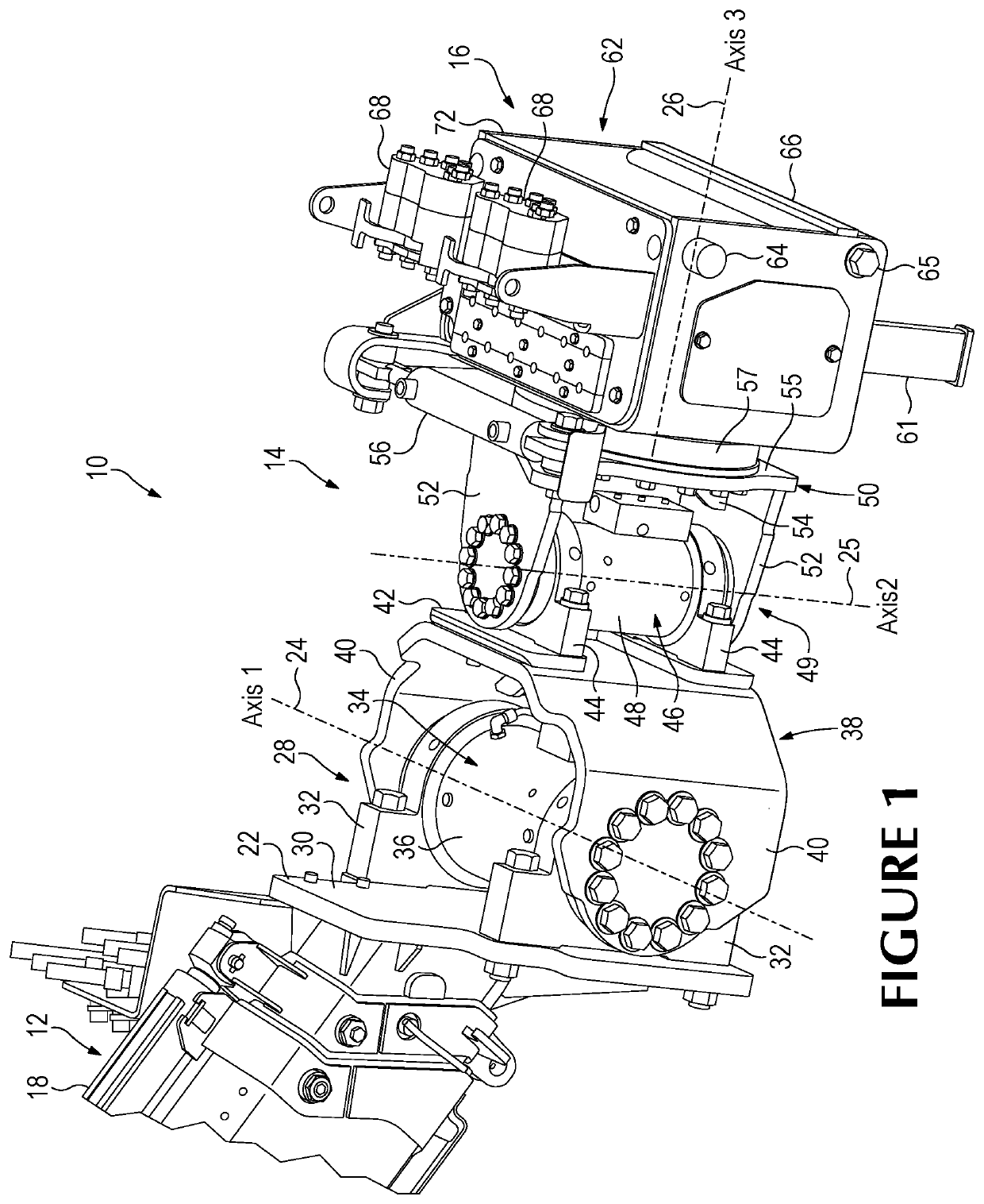
[0029]The present invention pertains to a manipulator for movably supporting one or more tools for conducting operations. A manipulator in accordance with the present invention can improve processes that are difficult, hazardous and / or time-consuming. The manipulator can, e.g., be used to assess conditions and / or perform critical operations.

[0030]In one embodiment, the manipulator is fluid driven, preferably hydraulic to be robust in varied environmental conditions, though other drives are possible for certain operations and / or conditions. A hydraulically-driven manipulator is less susceptible (e.g., as compared to electric drives) to failure in in-field operations where it may be subject to varied environmental conditions such as heat, cold, precipitation, dirt, fines, dust, smoke, corrosive materials, etc. A hydraulic drive is also able to provide substantial power by compact means (e.g., as compared to electric drives), which is useful for certain applications; one such example i...


PUM


Abstract

A joint secured to a manipulator for movably supporting a tool(s) for conducting operations, particularly those in the field is hydraulic to be robust in varied environmental conditions and / or provide sufficient power. The joint includes a base to secure the joint to the manipulator, an adapter to secure a tool to the joint, components movably joined together in close proximity with each other between the base and the adapter to define three non-parallel axes of movement for the adapter wherein two of the axes always intersect a third of the axes, and hydraulically-driven actuators to selectively move and hold the components about the axes.

Description

FIELD OF THE INVENTION[0001]The present invention pertains to a manipulator and systems for movably supporting a tool(s) for conducting operations and processes for operating the same.BACKGROUND OF THE INVENTION[0002]Workers are at times called upon to work in hazardous environments and / or to undertake difficult and / or time-consuming activities. Various tools have been developed to help make such operations safer, easier and / or quicker.[0003]As one example, in mining operations, ground-engaging wear parts are provided along the digging edge of a bucket of an excavating machine such as a dragline machine, cable shovel, face shovel, hydraulic excavator, bucket wheel excavator, and the like. The wear parts protect the underlying equipment from undue wear and, in some cases, also perform other functions such as breaking up the ground ahead of the digging edge. During use, the wear parts typically encounter heavy loading and highly abrasive conditions. As a result, they must be periodica...

Claims


Application Information

Patent Timeline
IPC IPC(8): E02F9/28
CPCB25J17/0283E02F3/3677E02F9/2891B25J15/04B25J13/006
Inventor CARPENTER, CHRISTOPHER M.CLARKE, RODNEY K.PAUL, DAVID M.
Owner ESCO GRP LLC
Why Eureka
Try Eureka