
Carrier head for chemical mechanical polishing device, including contact flap

a carrier head and mechanical polishing technology, applied in the direction of grinding head, grinding machine components, manufacturing tools, etc., can solve the problems of difficult manufacturing of the membrane, poor polishing uniformity, etc., and achieve the effect of suppressing the change of polishing uniformity

Pending Publication Date: 2019-11-28
KANG JOON MO
View PDF8 Cites 5 Cited by
  • Summary
  • Abstract
  • Description
  • Claims
  • Application Information

AI Technical Summary

Benefits of technology

The present invention is about a carrier head for a chemical mechanical polishing apparatus that can apply pressure independently to certain areas without a partitioning substrate receiving member. This helps to maintain consistent polishing across the entire substrate and prevents sudden changes in polishing uniformity at specific points.

Problems solved by technology

However, in this conventional carrier head, manufacturing the membrane becomes difficult as the number of inner flaps increases.
There have been also drawbacks of bad polishing uniformity induced by a pressure difference between chambers at zones where inner flaps are branched.

Method used


Image

  • Carrier head for chemical mechanical polishing device, including contact flap
  • Carrier head for chemical mechanical polishing device, including contact flap
  • Carrier head for chemical mechanical polishing device, including contact flap

Examples


Embodiment Construction

[0031]Hereinafter, preferred embodiments of the present invention will be explained with reference to the attached drawings. However, the invention is not limited to the disclosed embodiments hereinafter, but will be embodied in various forms. Rather, these embodiments of the present invention are provided in order to fully explain the present invention to those skilled in the art. Therefore, in the drawings, the sizes of components may be exaggerated for the clarity and convenience of the description.

[0032]In the description, when it is said that one member is connected “to a lower part” of another member, it means that one member may be connected to another member by contacting “lower part” as well as other members may exist between the two members and one member may be connected to yet another member. On the contrary, when it is said that one member is connected “directly to a lower part”, it means that another member may not exist between the two members. In the description, it ...


PUM


Abstract

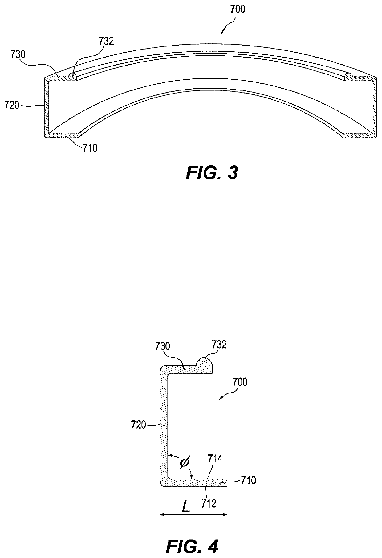
A carrier head for a chemical mechanical polishing apparatus is provided. The carrier head includes a base and a substrate receiving member connected to a lower part of the base. Inside of the substrate receiving member, at least one contact flap is connected to the lower part of the base. The at least one contact flap includes a connecting portion, a side portion extended downwardly from the connecting portion and a contact portion extended sidewardly from a bottom end of the side portion. Adjacent to the at least one contact flap, at least one wall structure is connected to the lower part of the base to limit an expansion of the at least one contact flap for a firm contact of the contact portion with an inner surface of the substrate receiving member by means of fluid pressure.

Description

TECHNICAL FIELD[0001]The present invention relates to a chemical mechanical polishing apparatus, and more particularly, to a carrier head comprising contact flap for applying polishing pressure to a substrate during a polishing process.BACKGROUND ART[0002]When manufacturing semiconductor or glass substrates, and fabricating integrated circuits, a need to polish or planarize the surface of a substrate at particular steps has been increased. As a technology to satisfy the need, a chemical mechanical polishing (CMP) has been widely used.[0003]In general, the CMP of a substrate is performed by attaching a polishing pad on a platen, mounting the substrate to a substrate receiving unit called a carrier head, and then, while applying slurry to the polishing pad, rotating the platen and carrier head simultaneously to generate friction between the polishing pad and the substrate.[0004]Basically, the carrier head comprises a base receiving motive power from a drive shaft and providing space i...

Claims


Application Information

Patent Timeline
Patent Type & Authority Applications(United States)
IPC IPC(8): B24B37/32
CPCB24B37/32H01L21/30625B24B41/00H01L21/304B24B41/002H01L21/3212
Inventor KANG, JOON MO
Owner KANG JOON MO
Learn More