
Multivalve member flow control apparatus and method

Inactive Publication Date: 2019-11-14
TLX TECH
View PDF0 Cites 3 Cited by
  • Summary
  • Abstract
  • Description
  • Claims
  • Application Information

AI Technical Summary

Benefits of technology

The invention provides a valve that can be opened and closed by a solenoid, which is a type of electromagnet. The valve has multiple valve members and solenoids that can independently move each member from a closed position to an open position to control the flow of fluid through the valve. The valve can increase or decrease the flow rate by moving the valve members from the closed position to the open position or from the open position to the closed position. This invention allows for more precise control over the flow of fluid through the valve.

Problems solved by technology

While such valves have proven suitable for proportional control, they are not without drawbacks.
Indeed, standard proportional valves which are solenoid actuated will exhibit hysteresis when moving from one control setting to another.
Such hysteresis results in non-linear changes in flow, and can lead to system unpredictability.
Further, because the aforementioned proportional valves vary flow coefficients via the position and orientation of the valve member along the flow path, the geometry of the valve member must be relatively precise, which drives the cost of such valves up.

Method used


Image

  • Multivalve member flow control apparatus and method
  • Multivalve member flow control apparatus and method
  • Multivalve member flow control apparatus and method

Examples


Embodiment Construction

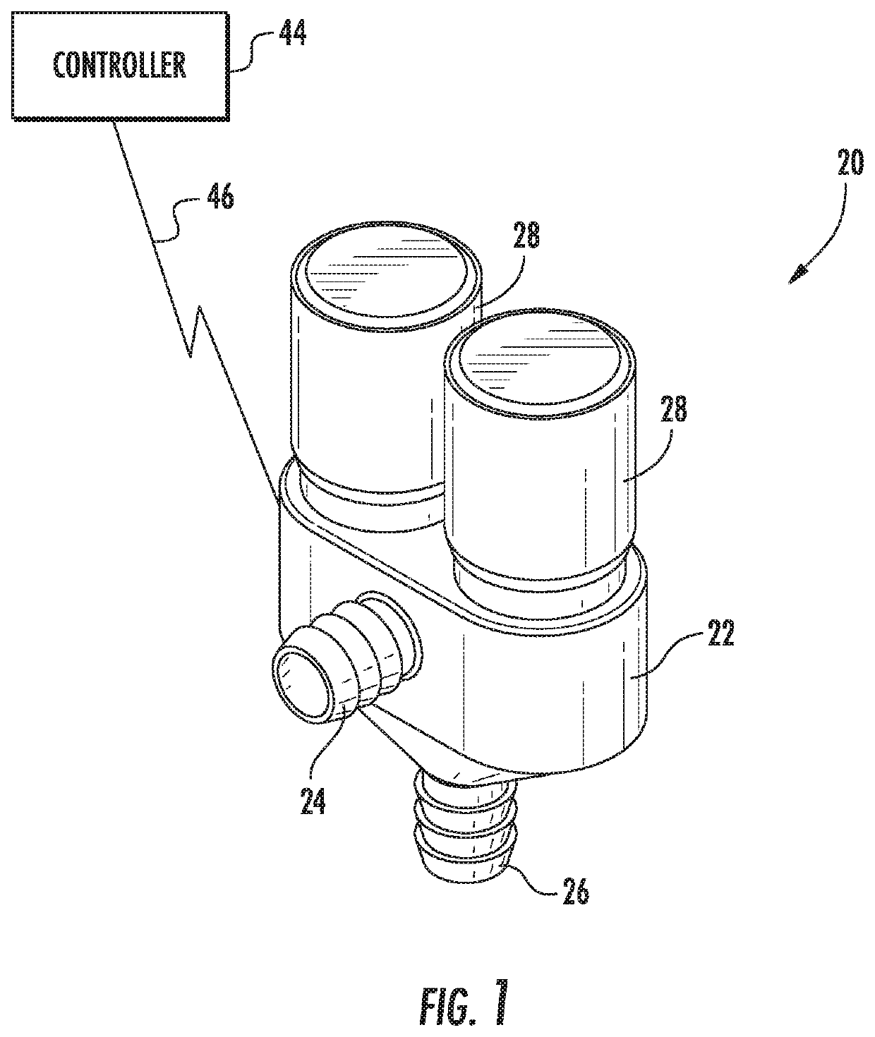
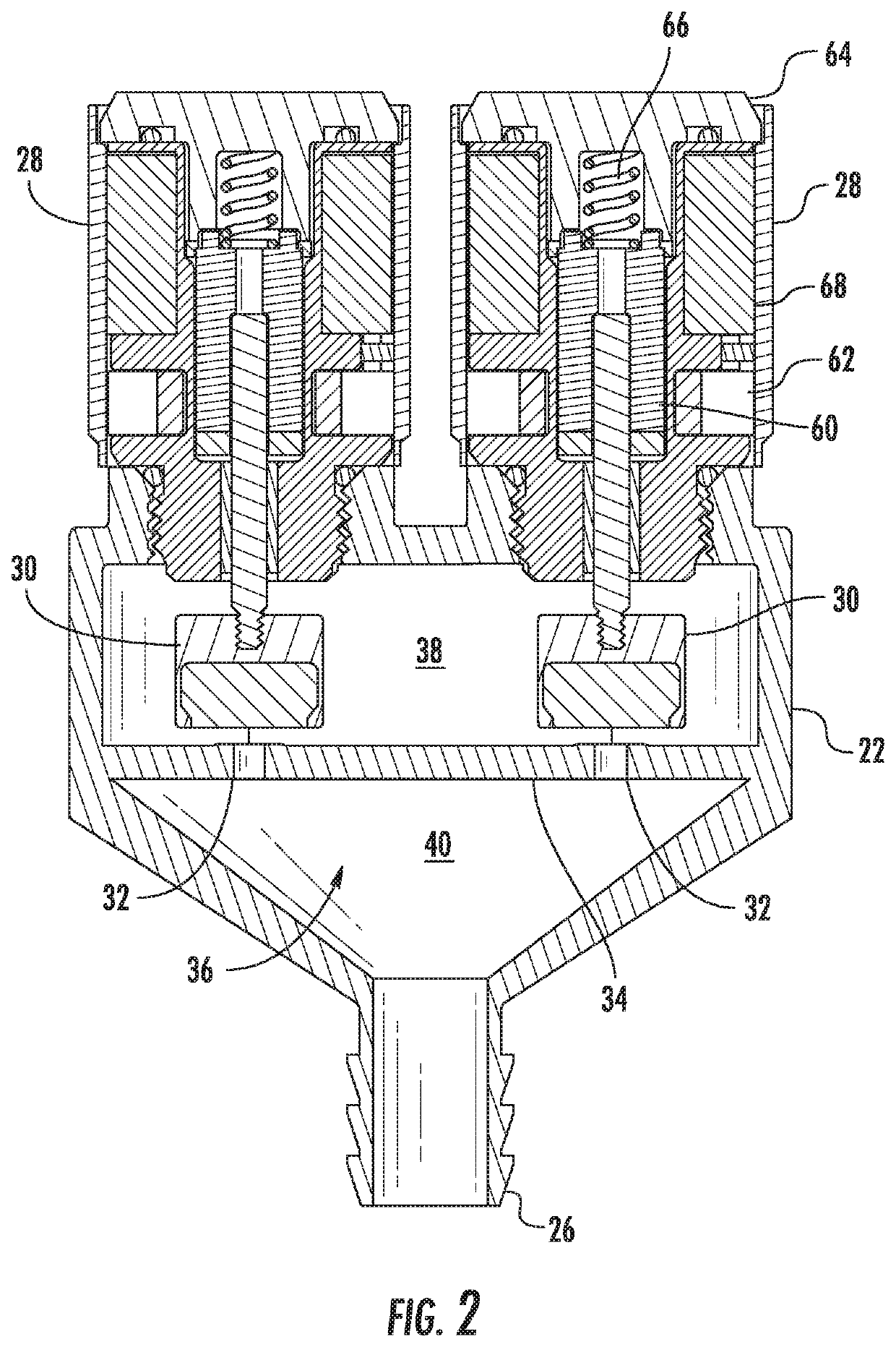
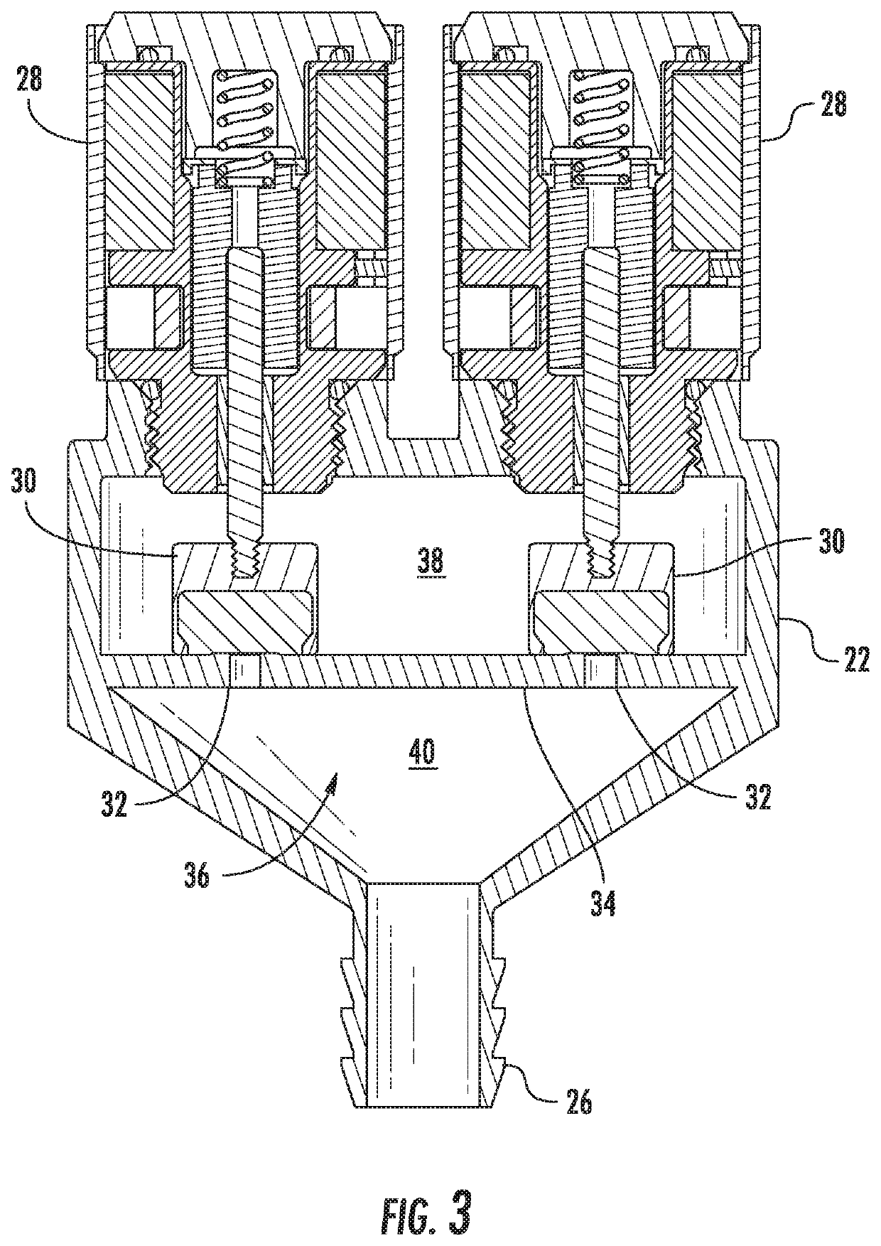
[0032]Turning now to the drawings, FIGS. 1-9 illustrate several different embodiments of a solenoid operated valve (also referred to herein simply as a valve) according to the teachings herein. FIG. 10 illustrates an example of the various incremental flow values which are possible using a solenoid operated valve constructed in accordance with the teachings herein.

[0033]As will be understood from the following, a solenoid operated valve constructed in accordance with the teachings herein utilizes multiple solenoids which each actuate their own respective valve member. In other words, there is a one-to-one relationship of valve members to solenoids. This same one-to-one relationship exists between the valve members and a plurality of passages arranged along a flow path through the valve. Each solenoid is operable to independently move its associated valve member from a closed position, where the valve member is seated against a partition wall defining the passage to entirely prevent ...


PUM


Abstract

A solenoid operated valve constructed in accordance with the teachings herein utilizes multiple solenoids which each actuate their own respective valve member. There is a one-to-one relationship of valve members to solenoids. This same one-to-one relationship exists between the valve members and a plurality of passages arranged along a flow path through the valve. Each solenoid is operable to independently move its associated valve member from a closed position, where the valve member is seated against a partition wall defining the passage to entirely prevent fluid flow through its associated passage (or only allow for a controlled leakage flow), and an open position, where the valve member allows fluid flow through its associated passage.

Description

CROSS-REFERENCE TO RELATED PATENT APPLICATIONS[0001]This patent application claims the benefit of U.S. Provisional Patent Application No. 62 / 670,136, filed May 11, 2018, the entire teachings and disclosure of which are incorporated herein by reference thereto.FIELD OF THE INVENTION[0002]This invention generally relates to valves, and more particularly to solenoid operated valves.BACKGROUND OF THE INVENTION[0003]Contemporary proportional control valves have the advantage of providing a broad range of control settings (e.g. output flow rates) by varying the flow coefficient of a single valve opening along a flow path through the valve. This variation may be so fine that a near infinite number of control settings along a continuous curve are possible for a given valve. This variation of the flow coefficient may be done by varying the linear or rotary position of a valve member arranged within the valve opening along the flow path. Examples of such linear variation may be seen from spoo...

Claims


Application Information

Patent Timeline
IPC IPC(8): F16K99/00F16K15/02F16K31/06
CPCF16K15/026F16K99/0028F16K31/0651F16K27/003F16K27/029F16K31/0655F16K31/0679
Inventor BYLE, FRANCIS R.BERGER, BRETT G.BIEHL, ANDREW PAULKUJAWSKI, CHRISTOPHER J.
Owner TLX TECH
Learn More