


Quick Research
Generate reliable direction feasibility study reports for your R&D in just a few steps.

Technical Q&A
Discover and master advanced knowledge NOW. Basics, ideas, possibilities, all at once.

Find Solutions
As an expert in R&D theories, this can generate solutions to your technical problems instantly.

Evaluate Feasibility
Analyze your overall solution with one click, know your potential R&D risks in advance.

Monitor Landscape
Get weekly tech updates, stay abreast of the latest tech innovations and key insights.
Analysis apparatus, imaging system, and storage medium
an analysis apparatus and imaging system technology, applied in the field of analysis apparatus, can solve the problem that the feature amount of the object cannot be efficiently analyzed, and achieve the effect of easy and efficient analysis of the obj
- Summary
- Abstract
- Description
- Claims
- Application Information
AI Technical Summary
Benefits of technology
Problems solved by technology
Method used
Image

Examples
example 1
[0053]Referring now to FIG. 6, a description will be given of an example 1 according to the present invention. FIG. 6 illustrates a spectral characteristic 601 of the spectroscope, spectral information 611 acquired by the spectroscope, and an estimated spectrum 612 estimated from the spectral information 611. In the spectral characteristic 601, the abscissa axis represents a wavelength and the ordinate axis represents a spectral intensity. In the spectral information 611, the abscissa axis represents wavelength information and the ordinate axis represents an intensity. In the estimated spectrum 612, the abscissa axis represents a wavelength and the ordinate axis represents an analytical reflectance.
[0054]As illustrated in the spectral characteristic 601, the spectroscope according to this example has four pieces of information of blue (B) of a dotted line, green (G) of a solid line, red (R) of a broken line, and infrared (IR) of an alternate long and short dash line. In other words,...
example 2
[0060]Referring now to FIG. 7, a description will be given of an example 2 according to the present invention. FIG. 7 illustrates a spectral characteristic 701 of the spectroscope, spectral information 711 acquired by the spectroscope, and estimated spectrum 712 estimated from the spectral information 711. In the spectral characteristic 701, the abscissa axis represents a wavelength and the ordinate axis indicates a spectral intensity. In the spectral information 711, the abscissa axis represents wavelength information and the ordinate axis represents an intensity. In the estimated spectrum 712, the abscissa axis represents a wavelength and the ordinate axis represents an analytical reflectance.
[0061]As illustrated in the spectral characteristic 701, the spectroscope according to this example can acquire three pieces of information of green (G) of a solid line, red (R) of a broken line, infrared (IR) of an alternate long and short dash line. In other words, the spectroscope accordin...
example 3
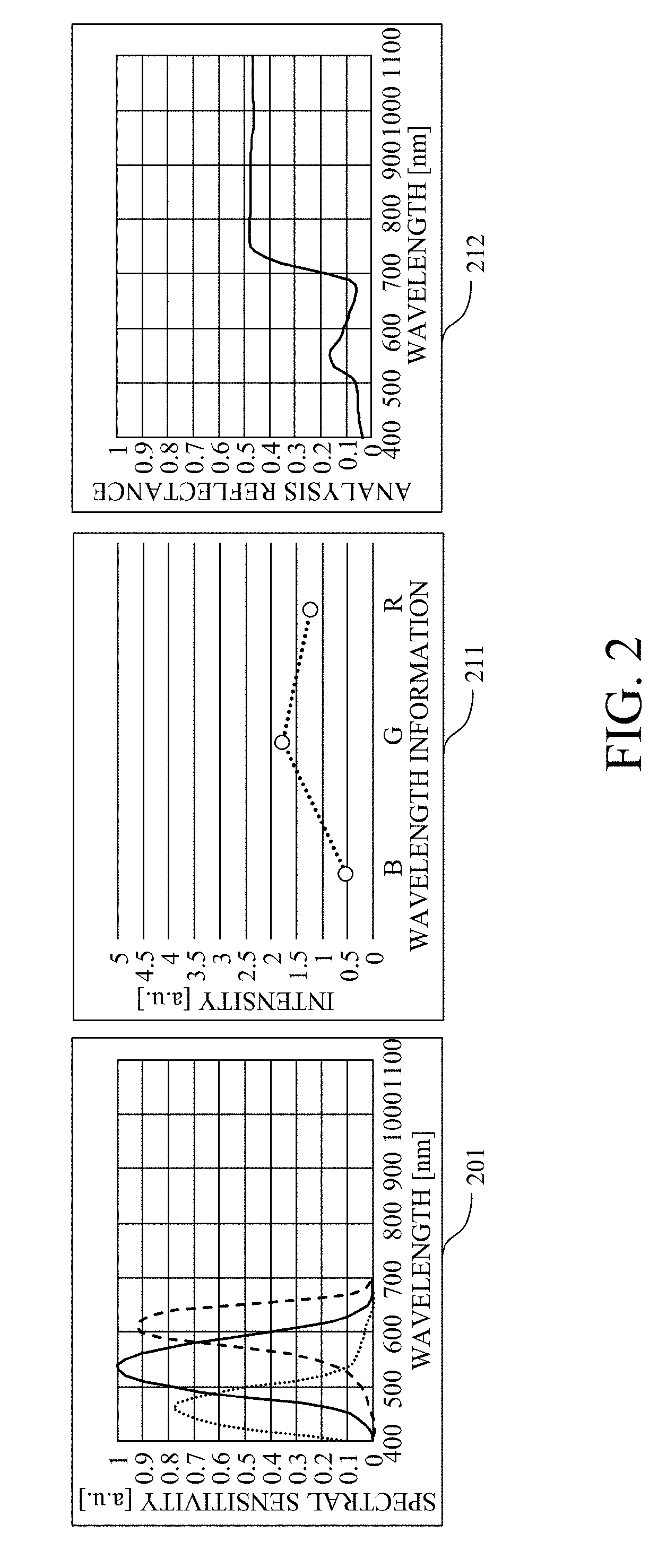
[0069]Referring now to FIG. 2, a description will be given of an example 3 according to the present invention. FIG. 2 illustrates a spectral characteristic 201 of the spectroscope, spectral information 211 acquired by the spectroscope, and an estimated spectrum 212 estimated from the spectral information 211. As illustrated in the spectral characteristic 201 of the spectroscope according to this example, three pieces of information of blue (B) of a dotted line, green (G) of a solid line, and red (R) of a broken line can be acquired. In other words, the spectroscope according to this example can acquire three points of information like the spectral information 211 as the spectrum 101.
[0070]Table 5 shows the coefficients k(k1, k2, k3) of the expression (5) relating to B, G, and R in this example. Table 6 shows average values Cavg of each of B, G and R. The analysis according to the expression (6) provides numerical values of t1=0.252, t2=0.138, and t3=−0.003. The calculation using the...
PUM
 Abstract
Description
Claims
Application Information
 - R&D Engineer
- R&D Manager
- IP Professional
- Industry Leading Data Capabilities
- Powerful AI technology
- Patent DNA Extraction
Browse by: Latest US Patents, China's latest patents, Technical Efficacy Thesaurus, Application Domain, Technology Topic, Popular Technical Reports.
© 2024 PatSnap. All rights reserved.Legal|Privacy policy|Modern Slavery Act Transparency Statement|Sitemap|About US| Contact US: help@patsnap.com