
Filter Pad for Rapid Removal

a filter pad and filter pad technology, applied in the field of filter pads, can solve the problems of limiting the handling of sludge, inconvenient cleaning, inconvenient cleaning, etc., and achieve the effects of convenient and quick removal of filter pads, convenient opening of fasteners, and convenient removal of filter pads

Active Publication Date: 2019-10-03
DAY ENTERPRISES LLC
View PDF2 Cites 0 Cited by
  • Summary
  • Abstract
  • Description
  • Claims
  • Application Information

AI Technical Summary

Benefits of technology

The invention is a container with a filter pad that can be easily removed and replaced. The filter pad can be opened to allow for the safe disposal of sediment and the removal of solids. The container has securing means to attach the filter pad to the container and to allow for easy removal. This design helps to prevent harm to operators and allows for efficient off-loading of solids.

Problems solved by technology

The waste is processed in the same unit in which it is hauled away and dumped, thus limiting the handling of the sludge.
The process is inefficient and sometimes dangerous.
There is no way to control the solids dumping from the container as the operator cuts the pad.
This procedure places the operator in a dangerous environment.

Method used


Image

  • Filter Pad for Rapid Removal
  • Filter Pad for Rapid Removal
  • Filter Pad for Rapid Removal

Examples


Embodiment Construction

[0028]The present invention can be understood more readily by reference to the following detailed description, examples, and claims, and their previous and following description. Before the present system, devices, and / or methods are disclosed and described, it is to be understood that this invention is not limited to the specific systems, devices, and / or methods disclosed unless otherwise specified, as such can, of course, vary. It is also to be understood that the terminology used herein is for the purpose of describing particular aspects only and is not intended to be limiting.

[0029]The following description of the invention is provided as an enabling teaching of the invention in its best, currently known aspect. Those skilled in the relevant art will recognize that many changes can be made to the aspects described, while still obtaining the beneficial results of the present invention. It will also be apparent that some of the desired benefits of the present invention can be obta...


PUM

PropertyMeasurementUnit
lengthaaaaaaaaaa
lengthaaaaaaaaaa
lengthaaaaaaaaaa

Abstract

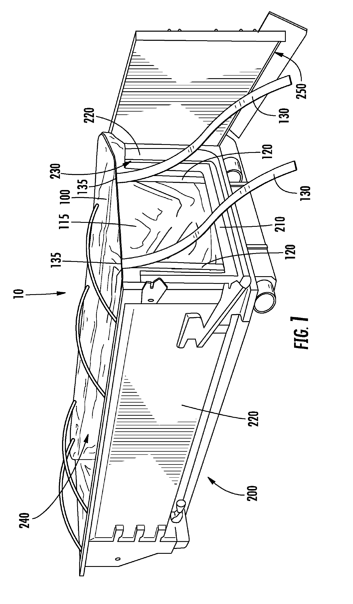
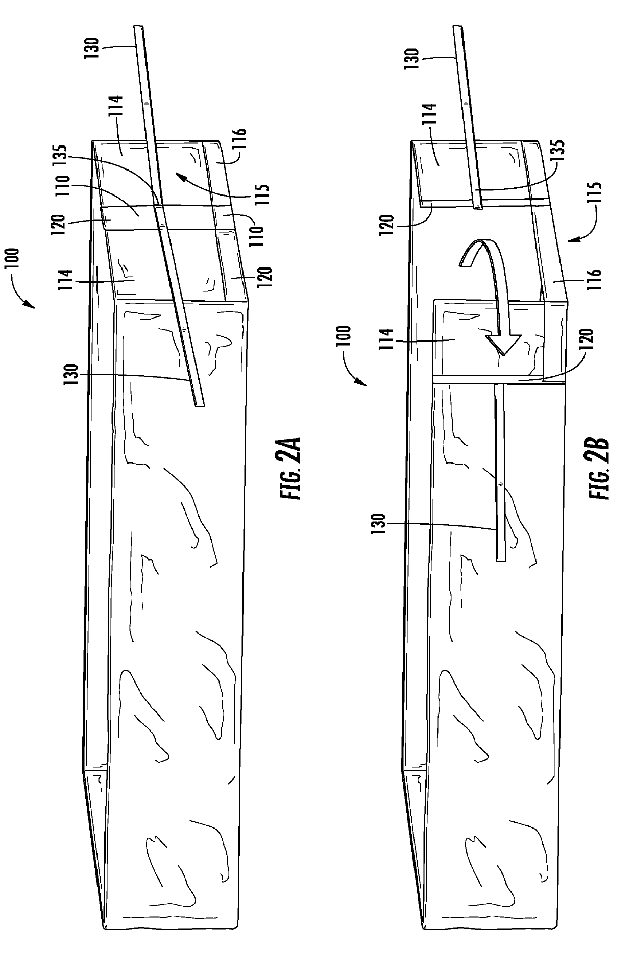
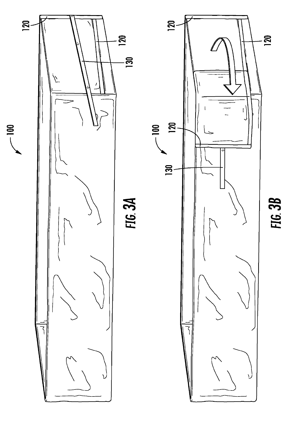
A filter pad for use in a dewatering container is presented. The filter pad is configured to fit within the interior cavity and substantially line the interior surfaces. Material, which is usually liquids and slurries, is added to the container with the filter in place and gravity is used to filter the sediment, while the water is released through a release nozzle. The solids are retained in the filter pad for later disposal. The filter pad has a portion that can be selectively opened and is configured for placement substantially adjacent the door to permit selective egress of contents of the interior cavity. The filter pad has an open upper end with securing members for cooperating with container hooks to provide safe and easy removal of the filter pad.

Description

CROSS REFERENCE TO RELATED APPLICATIONS[0001]This application is a continuation-in part of and claims the benefit of Ser. No. 16 / 009,740, filed Jun. 15, 2018, which is a continuation-in part of U.S. patent application Ser. No. 15 / 590,080, filed May 9, 2017, which claim the benefit of US Provisional Pat. Application No. 62 / 334,080 filed May 10, 2016, the disclosures of which are hereby incorporated by reference.FIELD OF THE INVENTION[0002]The present invention relates generally to filter pads, most particularly for use in a filter pad that fits standard dewatering containers.BACKGROUND OF THE INVENTION[0003]Generally, filter pads are universal enough that they fit standard containers. Commonly, dewatering containers are based on a roll-away dumpster design, also known in the industry as roll-off containers. There are basically two varieties of these dewatering containers: those that have permanent filters and those that use disposable filters.[0004]Container filters can be trailer-mo...

Claims


Application Information

Patent Timeline
Patent Type & Authority Applications(United States)
IPC IPC(8): B01D29/96B01D29/27
CPCB01D29/27B01D29/96B01D2201/40B01D2201/04
Inventor DAY, TIMOTHY
Owner DAY ENTERPRISES LLC
Learn More