
Near-infrared sensor cover

Active Publication Date: 2019-09-26
TOYODA GOSEI CO LTD
View PDF0 Cites 5 Cited by
  • Summary
  • Abstract
  • Description
  • Claims
  • Application Information

AI Technical Summary

Benefits of technology

The present invention provides a near-infrared sensor cover that can improve the clarity of near-infrared radiation while also capable of melting snow. The cover has a heater wire that prevents near-infrared radiation from passing through the cover and reflects it instead. By extending the straight line portions of the heater wire along the main paths of the scanning path, the amount of reflected near-infrared radiation is minimized. This results in a detection function of the near-infrared sensor decreasing. Overall, this invention provides a cover that allows for better detection of near-infrared radiation while also addressing the issue of snow accumulation.

Problems solved by technology

Further, the amount (reflection amount) of near-infrared radiation reflected by the heater wire is restricted to an allowable value.

Method used


Image

  • Near-infrared sensor cover
  • Near-infrared sensor cover
  • Near-infrared sensor cover

Examples


Embodiment Construction

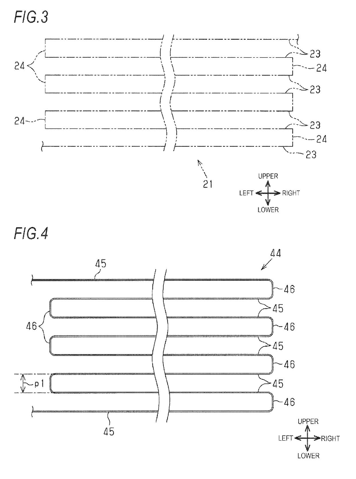
[0027]Hereinafter, an embodiment of a near-infrared sensor cover is described with reference to FIGS. 1A to 6C. In the following description, a forward direction of a vehicle is described as front, and a backward direction is described as rear. An upper-lower direction indicates an upper-lower direction of the vehicle, and a left-right direction, which is a vehicle width direction, coincides with a left-right direction of the vehicle during forward movement.

[0028]As illustrated in FIGS. 1 and 2, near-infrared sensors 11 are attached to four corners (right front portion, left front portion, right rear portion, and left rear portion) of a vehicle 10 in a plan view. FIG. 2 illustrates only the near-infrared sensor 11 attached to the left front portion of the vehicle 10. The near-infrared sensors 11 in the four corners have the same configuration. Therefore, only the near-infrared sensor 11 attached to the left front portion of the vehicle 10 is described below, and descriptions of the ...


PUM


Abstract

There is provided a near-infrared sensor cover to be applied to a near-infrared sensor including a transmitting unit that transmits near-infrared radiation and a receiving unit that receives near-infrared radiation reflected by an object. The near-infrared sensor cover includes a cover main body portion disposed with a thickness direction thereof to be coincide with a transmission and reception direction of the near-infrared radiation and covering the transmitting unit and the receiving unit, and a heater wire disposed on the cover main body portion to generate heat when energized. The heater wire includes plural straight line portions that extend in parallel to each other and plural connection portions that connect end portions of adjacent straight line portions. An interval between adjacent straight line portions ranges from 3 mm to 10 mm, and a diameter of the heater wire ranges from 0.01 mm to 0.2 mm.

Description

CROSS-REFERENCE TO RELATED APPLICATION[0001]This application claims priority from Japanese Patent Application No. 2018-056640, filed on Mar. 23, 2018, the entire subject matter of which is incorporated herein by reference.TECHNICAL FIELD[0002]The present invention relates to a near-infrared sensor cover that covers a near-infrared transmitting unit and a near-infrared receiving unit of a near-infrared sensor.BACKGROUND ART[0003]A near-infrared radar device may be provided in a vehicle so as to detect a distance from or a relative speed with respect to an object including a preceding vehicle, a pedestrian, and the like using near-infrared radiation. A near-infrared sensor constituting a part of the near-infrared radar device includes a near-infrared transmitting unit and a near-infrared receiving unit. The transmitting unit and the receiving unit are covered with a near-infrared sensor cover through which near-infrared radiation penetrates. In the near-infrared sensor, near-infrared ...

Claims


Application Information

Patent Timeline
IPC IPC(8): G01S7/481G01S17/93G01S17/931
CPCG01S17/93G01S7/4817G01S7/4814G01S7/4813G01S17/931H05B3/84H05B2203/014H05B3/145H05B3/845H01Q1/02
Inventor OKUMURA, KOJIOKAWA, SHINTAROANDO, HIROAKIMAEDA, HIDETOIIMURA, KIMIHIRO
Owner TOYODA GOSEI CO LTD
Learn More