Vehicle chassis front section structure

Active Publication Date: 2019-09-12
HONDA MOTOR CO LTD
View PDF0 Cites 1 Cited by
  • Summary
  • Abstract
  • Description
  • Claims
  • Application Information

AI Technical Summary

Benefits of technology

The patent allows for a stable buckling deformation in the case of a vehicle crash while using a simple structure. It also reduces the size and weight of the reinforcement member.

Problems solved by technology

Here, when a stiffener for reinforcement is attached to the upper curved section for the purpose of securing rigidity and when a desired bend starting point overlaps a position of this stiffener attached, there is a risk of failure to bend stably at the desired bend starting point because an adequate difference is not created between section strength of the wheel housing lower member at the desired bend starting point and section strength of the wheel lower member at a point in front of or in the rear of. the position of the stiffener attached.
However, this structure leads to an increase in size of the stiffener and thus results in an increase in weight of a vehicle.

Method used


Image

  • Vehicle chassis front section structure
  • Vehicle chassis front section structure
  • Vehicle chassis front section structure

Examples


Embodiment Construction

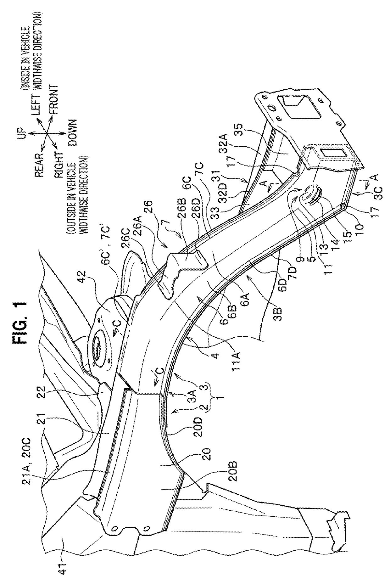
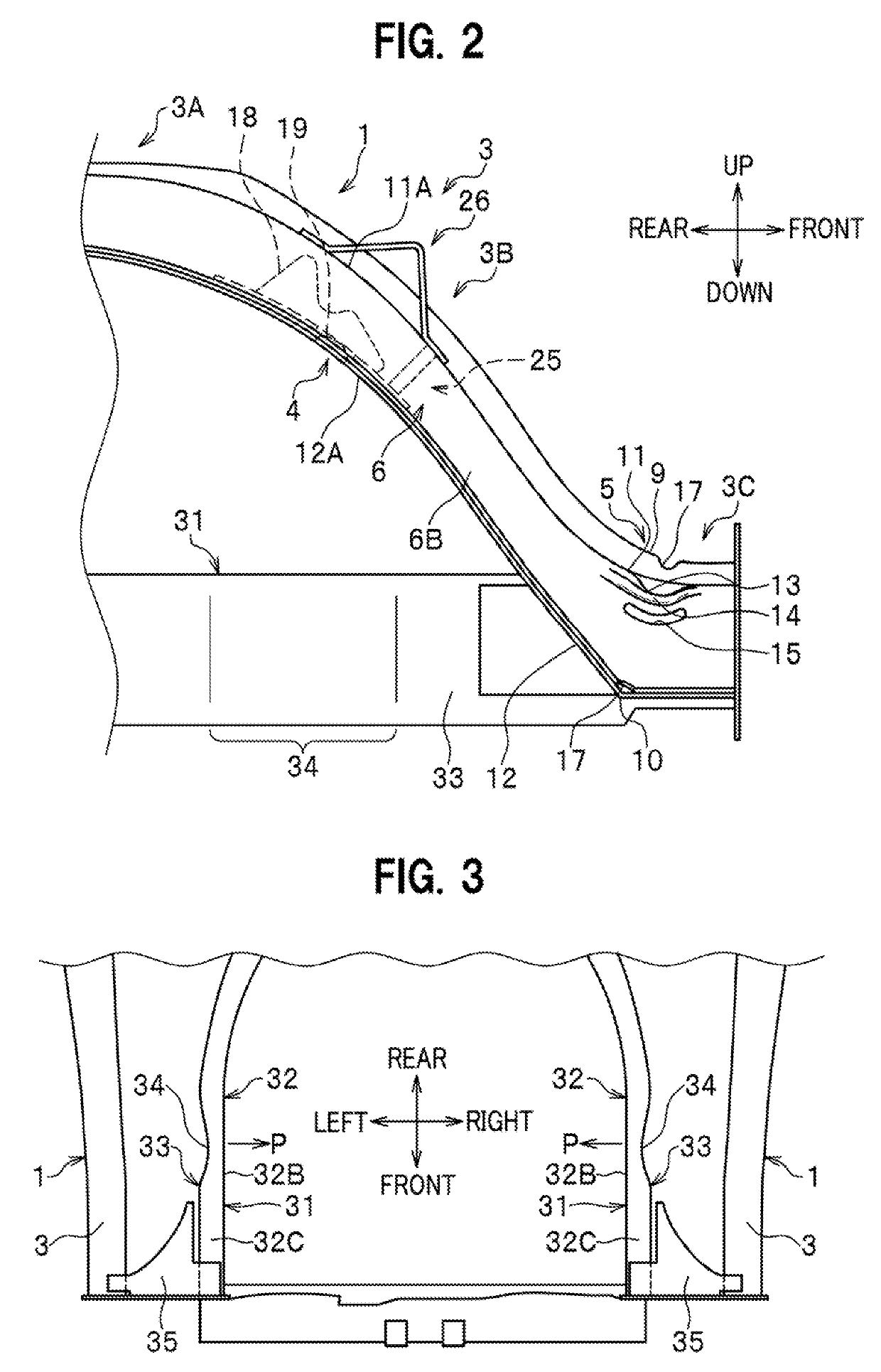
[0032]A description will be given of a mode of applying the present invention to a frame structure of a vehicle chassis front section of an automobile. Referring to FIGS. 1 to 5, lateral-section frames 1 and front side frames 31 are disposed on two sides in a vehicle widthwise direction of a vehicle to form right and left pairs. As shown in FIG. 3, each lateral-section frame 1 is disposed on outside in the vehicle widthwise direction of the corresponding front side frame 31. FIGS. 1, 2, and 5 illustrate the lateral-section frame 1 and the front side frame 31 located on the right side of the vehicle. While the following description will discuss the lateral-section frame 1 and the front side frame 31 disposed on the right side of the vehicle, those on the left side of the vehicle have the same structures except that they are formed into symmetrical shapes to the foregoing.

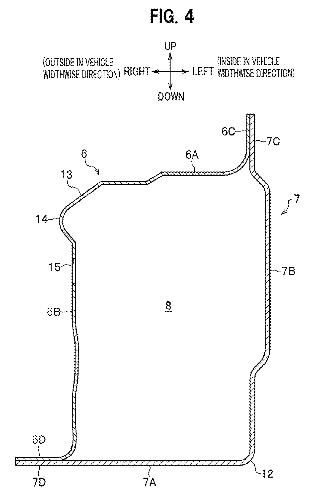
[0033](Lateral-Section Frame 1)

[0034]The lateral-section frame 1 includes: a wheel housing upper member 2 with its...


PUM


Abstract

A lateral-section frame includes a wheel housing upper member, the rear end of which is connected to a front pillar, and a wheel housing lower member extending from the wheel housing upper member via an upper curved section and a lower curved section in a manner such that the front end thereof extends forward and downward to a substantially identical location as does the front end of the front side frame. A stiffener extending forward and rearward to sandwich the upper curved section is attached to the interior of the wheel housing lower member, and the stiffener includes a front rigid section and a rear rigid section attached to a lower surface section and an inside surface section to sandwich an inside ridge therebetween; and a connecting section connecting the front rigid section and the rear rigid section and being attached to at least the inside surface section.

Description

TECHNICAL FIELD[0001]The present invention relates to a vehicle chassis front section structure of an automobile or the like.BACKGROUND ART[0002]It is common practice that a wheel housing lower member is set to have a section having a relatively low strength in advance so as to absorb collision energy in case of a front collision of a vehicle by bringing this section to buckling. In general, a wheel housing lower member is provided with an upper curved section and a lower curved section and formed into a shape that extends in a vehicle longitudinal direction. Here, the upper curved section and the lower curved section are used collectively as a buckling section.[0003]Here, when a stiffener for reinforcement is attached to the upper curved section for the purpose of securing rigidity and when a desired bend starting point overlaps a position of this stiffener attached, there is a risk of failure to bend stably at the desired bend starting point because an adequate difference is not c...

Claims


Application Information

Patent Timeline
IPC IPC(8): B62D25/20B62D21/15
CPCB62D25/2018B62D21/157B62D25/2036B62D21/152B62D25/082B62D25/088B62D25/08
Inventor KONDO, TAKEHIROKAMADA, TOMOHITO
Owner HONDA MOTOR CO LTD
Why Eureka
Try Eureka