
Control arrangment for a generator

a control arrangement and generator technology, applied in the direction of optimizing machine performance, engine control parameters, motors, etc., can solve the problems of reducing the number of channels, affecting the efficiency of the operation, so as to achieve the effect of higher efficiency

Active Publication Date: 2019-09-05
SIEMENS GAMESA RENEWABLE ENERGY AS
View PDF1 Cites 5 Cited by
  • Summary
  • Abstract
  • Description
  • Claims
  • Application Information

AI Technical Summary

Benefits of technology

The invention provides a method to reduce harmonic losses in a multiple channel three-phase machine when it operates at reduced channel operation with a large unbalance in the electromagnetic circuit. This prevents the magnet from overheating and demagnetization, and increases the machine output power.

Problems solved by technology

However, such a machine could become less electromagnetically balanced when operated with reduced number of channels, for example, the single channel (three-phase) operation.
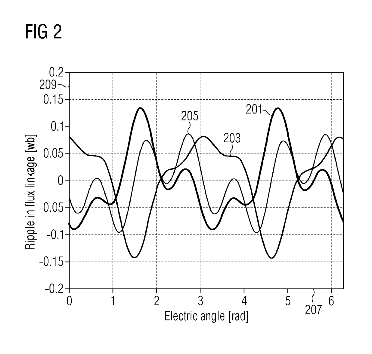
In particular, the harmonics in the airgap flux linkage will induce more losses in the rotor magnet and thus potential overheating and demagnetisation of the magnets, which becomes one of the key limiting factors in power production.
For different reasons, one or more of the multiple sets of stator windings may be idle or disconnected from their converters, for example due to a failure in the corresponding converters.
Adjusting the harmonic Iq current may change the generator torque ripple which may cause noise and vibration issue of the generator.

Method used


Image

  • Control arrangment for a generator
  • Control arrangment for a generator
  • Control arrangment for a generator

Examples


Embodiment Construction

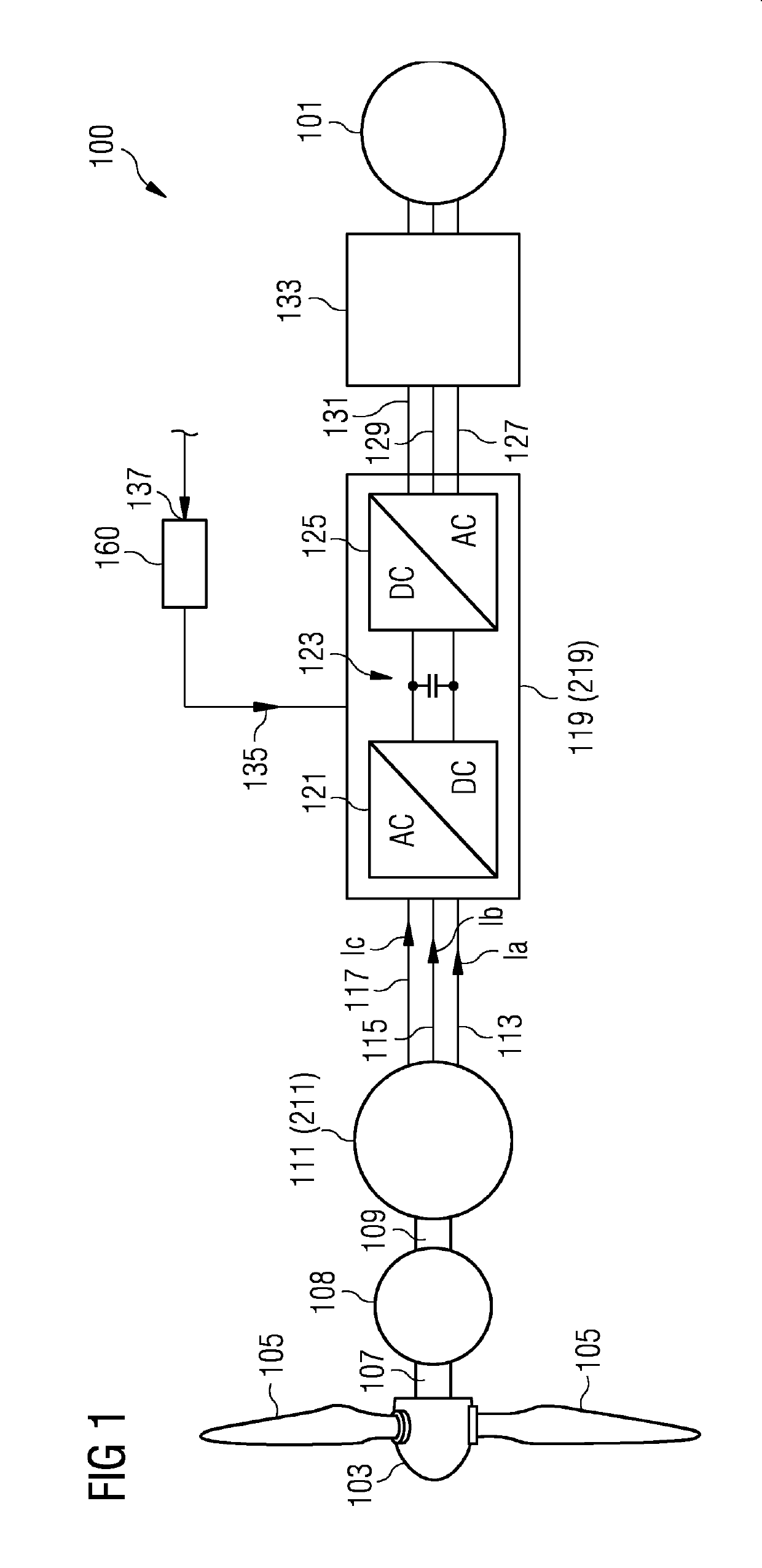
[0079]FIG. 1 illustrates in a schematic form a wind turbine 100 which provides electric energy to a utility grid 101.

[0080]The wind turbine comprises a hub 103 to which plural rotor blades 105 are connected. The hub is mechanically connected to a main shaft 107 whose rotation is transformed by a gear box 108 to a rotation of a secondary shaft 109, wherein the gear box 108 may be optional. The main shaft 107 or the secondary shaft 109 drives a generator 111 (or 211 for the second channel) which may be in particular a synchronous permanent magnet generator providing a power stream in the three phases or windings 113, 115 and 117 to a converter 119 which comprises a AC-DC portion 121, a DC-link 123 and a DC-AC portion 125 for transforming a variable AC power stream to a fixed frequency AC power stream which is provided in three phases or windings 127, 129, 131 to a wind turbine transformer 133 which transforms the output voltage to a higher voltage for transmission to the utility grid ...


PUM


Abstract

Provided is a control arrangement for controlling an electrical machine, including: a fundamental current controller, at least one harmonic flux controller related to a harmonic of an electrical frequency of the electrical machine, a summation system for adding voltage commands to obtain a summed voltage command based on which the electrical machine.

Description

CROSS-REFERENCE TO RELATED APPLICATIONS[0001]This application claims priority to PCT Application No. PCT / EP2017 / 071986, having a filing date of Sep. 1, 2017, which is based on German Application No. 10 2016 217 887.3, having a filing date of Sep. 19, 2016, the entire contents both of which are hereby incorporated by reference.FIELD OF TECHNOLOGY[0002]The following relate to a control arrangement for controlling an electrical machine, and to a generator system and a wind turbine.BACKGROUND[0003]In a wind turbine, a rotation shaft at which plural rotor blades are connected drives a generator in order to generate electric energy. Conventionally, a converter, in particular full scale frequency converter, is connected to output terminals of the generator. The frequency converter is widely used to interface the generator to a utility grid to which plural consumers of electricity are connected.[0004]When a multiple-channel three-phase PM machine is designed, the electromagnetic circuit is ...

Claims


Application Information

Patent Timeline
IPC IPC(8): H02P21/05H02P21/22F03D9/25F03D7/02
CPCH02P21/05H02P21/22F03D9/25F03D7/0272F05B2270/30F05B2220/706F05B2270/20F05B2270/10H02P2101/15H02P9/102H02P21/141H02P25/22H02P29/50Y02E10/72
Inventor DENG, HENGFREIRE, NUNO MIGUEL AMARALWU, ZHAN-YUAN
Owner SIEMENS GAMESA RENEWABLE ENERGY AS
Learn More