
Devices and methods for image-guided percutaneous cardiac valve implantation and repair

a technology of percutaneous cardiac valve and imageguided technology, which is applied in the field of imageguided percutaneous cardiac valve implantation and repair, can solve the problems of no good medical treatment, high burden of valve disease in the developing world, and become an important public health problem

Active Publication Date: 2019-08-22
INNOSCION
View PDF0 Cites 0 Cited by
  • Summary
  • Abstract
  • Description
  • Claims
  • Application Information

AI Technical Summary

Benefits of technology

[0007]A trans-apical approach according to the present invention will avoid those issues and these of prior art techniques and apparatus but may require mini-surgery that is minimally invasive, but on the other hand, requires considerable operating room time, Both femoral and apical or atrial approaches may use separate intra-procedure ultrasound (or other) imaging, A trans-apical system that does not need surgery, prevents strokes and provides built-in imaging, and intra-procedure monitoring will allow safe and reliable deployment of cardiac valves and significantly expand the use of these transcatheter valves.
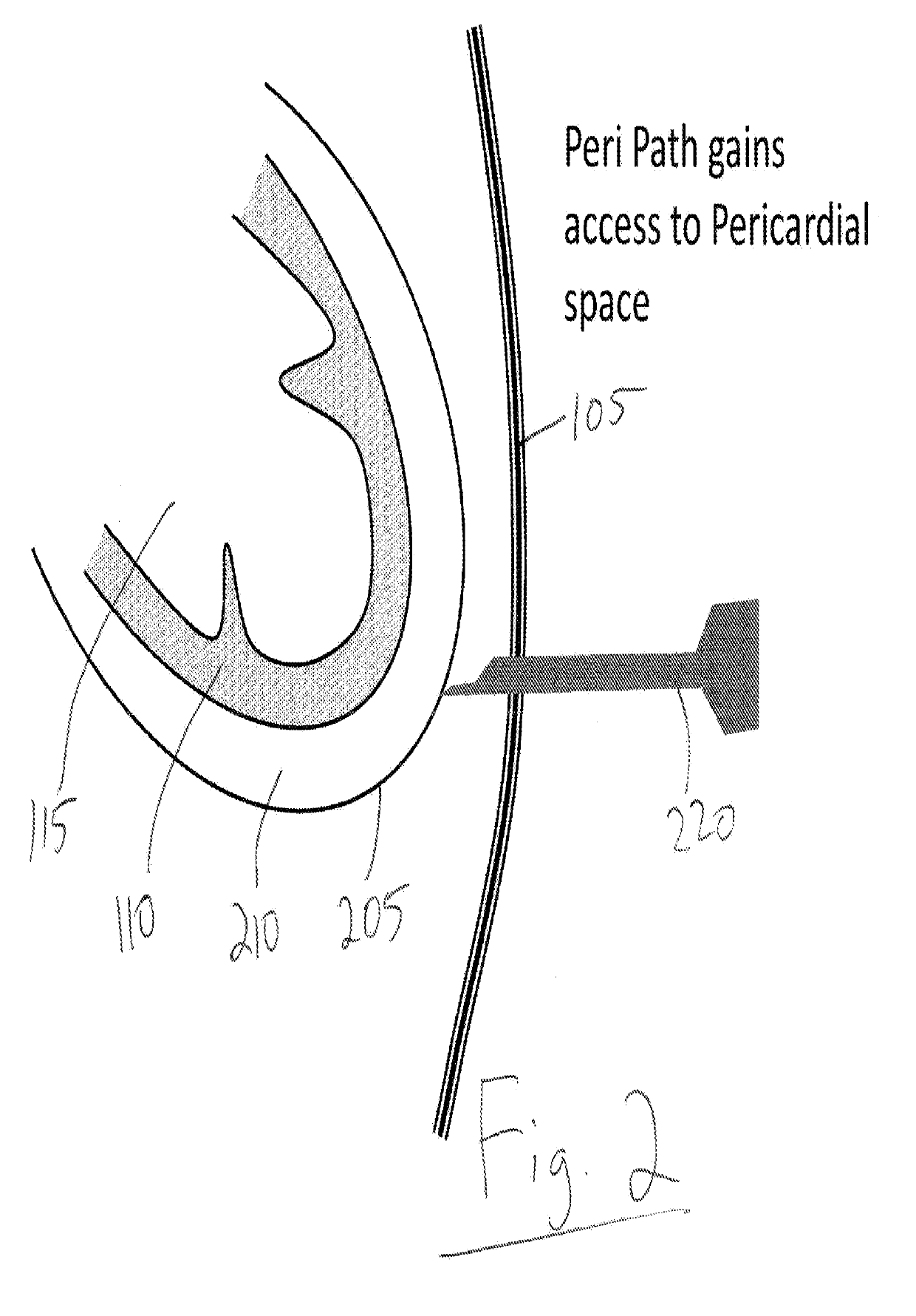
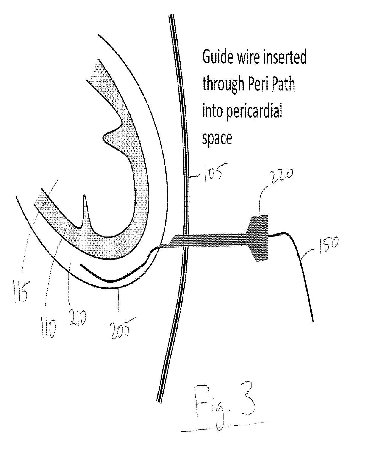
[0011]Once the pericardial space has been penetrated via the sheath, the guide wire may be removed leaving the sheath displaced at an angle (a sharp angle less than ninety degrees) and entering the pericardial space. The operating space between the outer and inner pericardial linings may be expanded by injecting saline or other solution to create an operating space volume using a hollow needle moved through the sheath, Through the sheath and with ultrasound guidance, a periport (pericardial space portal) now comprising an assembly of a particulate aortic filter (undeployed) followed by a prosthesis comprising a replacement heart valve may be deployed via first and second tubular pushers surrounding a guide wire. To provide ultrasound guidance, an imaging transducer may be moved from a lengthwise position along the periport to a position that is angled, for example, at an angle less than orthogonal with the periport to place the ultrasound imager at a location with a directed imaging zone that captures the heart and subsequent, use of the periport. The ultrasound imager should have sufficient depth to reach within the heart and have sufficient resolution to view heart parts especially the heart valve to be replaced and beyond the valve to where a filter such as an ascending aortic filter may be utilized to prevent stroke demonstrated as problematic in the prior art.
[0012]To achieve the goals of depth of ultrasound vision, the ultrasound transducer may be calibrated within a range of twenty-five kHz to 100 MHz and, more, particularly, operate in a range between one and ten MHz. As taught in prior patent applications of the inventor, the image guided catheter may comprise a plurality of imaging lumens in which transducers, sheaths, guide wires, delivery systems and tools may be replaced in real time within a particular lumen under vision. in addition, as discussed above, it is important to prevent leaks from the pressure zone of the heart ventricle by inserting the periport device at an angle once in the pericardial space (which may be opened with saline solution (as discussed above) and its tip bent to point to the ventricular space at an angle at its apex to prevent leakage. Through the bent periport located just outside the ventricular apex, a needle may be introduced so as to puncture the ventricular apex of the heart at a sharp angle to minimize flow of blood from the ventricle into the pericardial space and then the periport may be straightened for continuing the procedure. Then, the periport is advanced through the left Ventricle apex using the needle as a guide wire and at an angle to prevent blood loss. The periport is deployed (moved) into the ventricular space. The needle may then, having served its purpose, be removed by retraction through the periport and out the chest wall.
[0015]Once the prosthesis and replacement valve are in place and positioned to Ell the entire space taken by the defective valve, ultrasound may be used to look for leakage of blood around the prosthetic valve and the valve expanded in size, like a balloon, or change shape from an elongated cylinder to a fat, short cylinder to fill the space entirely that was left by the defective, pushed aside valve. Once the new valve is placed, the aortic filter is collapsed like an umbrella for removal capturing any particulate matter inside, and may be removed by the plastic tube or pusher that now becomes a puller. When pulling the collapsed filter out of the heart, the J-tip collapses, is automatically straightened and so the collapsed filter (like a collapsed umbrella) is easily pulled out through the prosthetic valve along with the, for example, J-tipped guide wire.
[0016]The heart valve prosthesis is now capable of functioning normally replacing the defective valve. Remaining still, at the ventricular apex is the periport which is now used for delivery’ of a closure device comprising two umbrella-like pads, a distal pad and a proximal pad for closing the myocardium, for example, at the ventricular apex. The closure device then comprises a distal pad a proximal pad and wires used for installation, control of opening and closing and, in particular, closing the angled hole remaining at the ventricular apex of the myocardium, The distal pad is pushed through the myocardial opening, opened and then pulled to a position closing about the myocardial angled opening. Then, the proximal pad is opened and is pushed upward until it reaches the myocardium under ultrasound vision. The two reverse, open “umbrella” pads, the distal and proximate pads, effectively close the angled myocardium entry point so as to preclude any release of blood through the ventricular apex.

Problems solved by technology

As the population ages, this condition becomes an important public health problem.
There are no good medical therapies for valve disease hence in moderate to severe valve disease with, symptoms, the definitive treatment is valve repair or replacement.
Additionally, the burden of valve disease in the developing world remains high.

Method used


Image

  • Devices and methods for image-guided percutaneous cardiac valve implantation and repair
  • Devices and methods for image-guided percutaneous cardiac valve implantation and repair
  • Devices and methods for image-guided percutaneous cardiac valve implantation and repair

Examples


Embodiment Construction

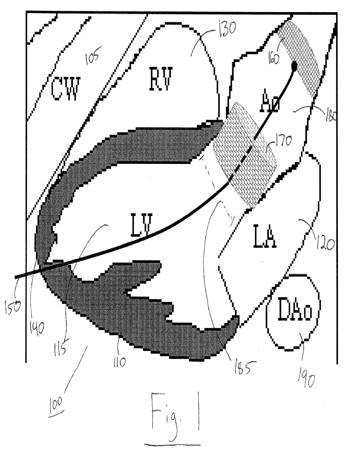
[0073]aspects summarized above can be embodied in various forms. The. following description shows, by way of illustration, combinations and configurations in which the aspects can be practiced by the various image guided catheter-like devices discussed and utilized in sequence in a method for replacing or repairing a defective heart valve, it is understood that the described aspects and / or embodiments are merely examples, it is also understood that other aspects and / or embodiments can be utilized, and that structural and functional modifications can be made, without departing from the scope of the present disclosure. Furthermore, modifications to the method(s) of repair and replacement of cardiac valves should not be considered limited in scope to the disclosure but may involve known processes and devices and procedures to those of ordinary skill in the art

[0074]Referring to FIG. 1, there is shown a drawing in two dimensions of the: heart 100 and. chest wall (CW) 105 which may be pe...


PUM


Abstract

Devices and methods for ultrasound image-guided percutaneous, cardiac valve implantation and repair comprise, in combination, a plurality of devices including but not limited to an ultrasound-image guided catheter, a pericardial sheath, a cardiac-valve delivery system and an ascending aortic filter. An image-guided catheter is utilized to introduce via an introducer needle and a guide wire a pericardium portal for permitting entry from the chest wall to inside the pericardial space between the pericardial outer lining and inner lining. The pericardium portal permits the use of ultrasound vision to locate a site proximate the left ventricular apex, for introduction of a sheath via a .myocardium needle into the left ventricular space at an angle and avoiding any coronaries or vessels. A first delivery system permits placement of at least one aortic filter which collects any emboli, particulate matter, plaque and prevents such matter travelling via the ascending aorta to the brain, causing a stroke. A second delivery system permits placement of an aortic and / or mitral valve replacement or repair using several types of repair tools.

Description

TECHNICAL FIELD[0001]The invention, relates to the field of cardiac valve replacement and repair and, in particular, to a plurality of devices and a sequential method for implanting via ultrasound and other image guidance a percutaneous cardiac valve, for example, the aortic valve between the left ventricle outflow tract and the ascending aorta or the mitral valve.BACKGROUND OF THE INVENTION[0002]There is an increasing focus on the percutaneous treatment of valve disease / Mitral valve disease is very common. Rheumatic mitral valve disease is estimated to affect close to 16 million individuals worldwide. [See WHO Tech Series #924, 20041 with about 300,000 new cases per year and surgery indicated in approximately one million patients per year. Mitral regurgitation is common, affecting more than approximately four million Americans—nearly one in ten people aged seventy-live and older. [See https: / / www.dicardiology.com. Aortic valve disease is also common and its prevalence increases wit...

Claims


Application Information

Patent Timeline
Patent Type & Authority Applications(United States)
IPC IPC(8): A61B34/20A61B10/04A61B8/08A61F2/24A61B17/34A61B8/12A61B8/00
CPCA61B34/20A61B10/04A61B8/0883A61F2/2427A61B17/3403A61B8/0841A61B8/12A61B8/445A61B2017/00247A61B17/3421A61F2/013A61F2230/0067A61B2034/2063A61B2017/3413A61B2017/00575A61B2017/00243A61B17/3478A61M25/09A61B2017/00783A61B2090/3782A61B2017/00606A61B2017/00592A61B17/0057A61B2017/00619A61B2017/00623A61B2017/12018A61B2017/06171A61B2017/06052A61F2/0105
Inventor ABRAHAM, THEODORE P.
Owner INNOSCION
Learn More