
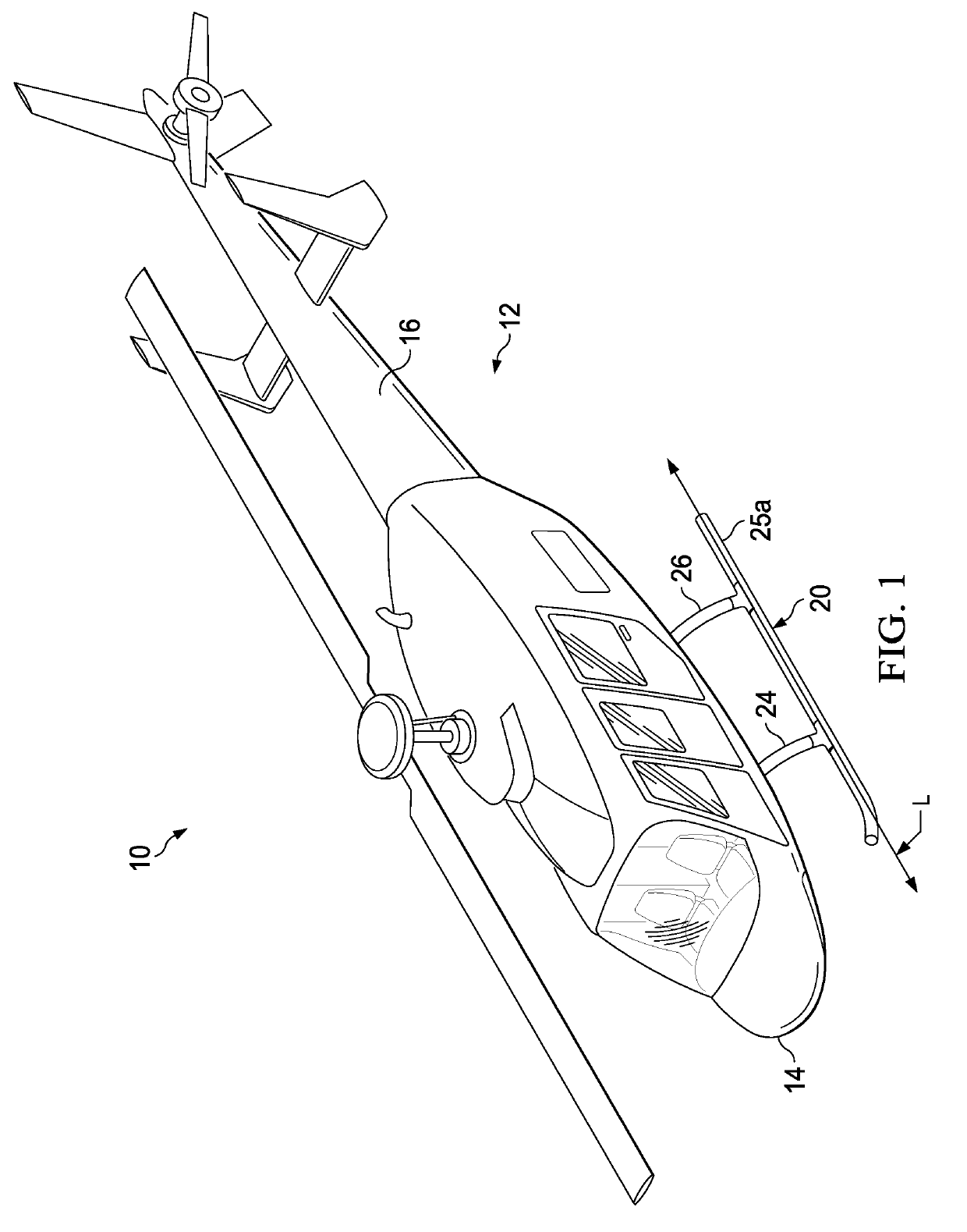
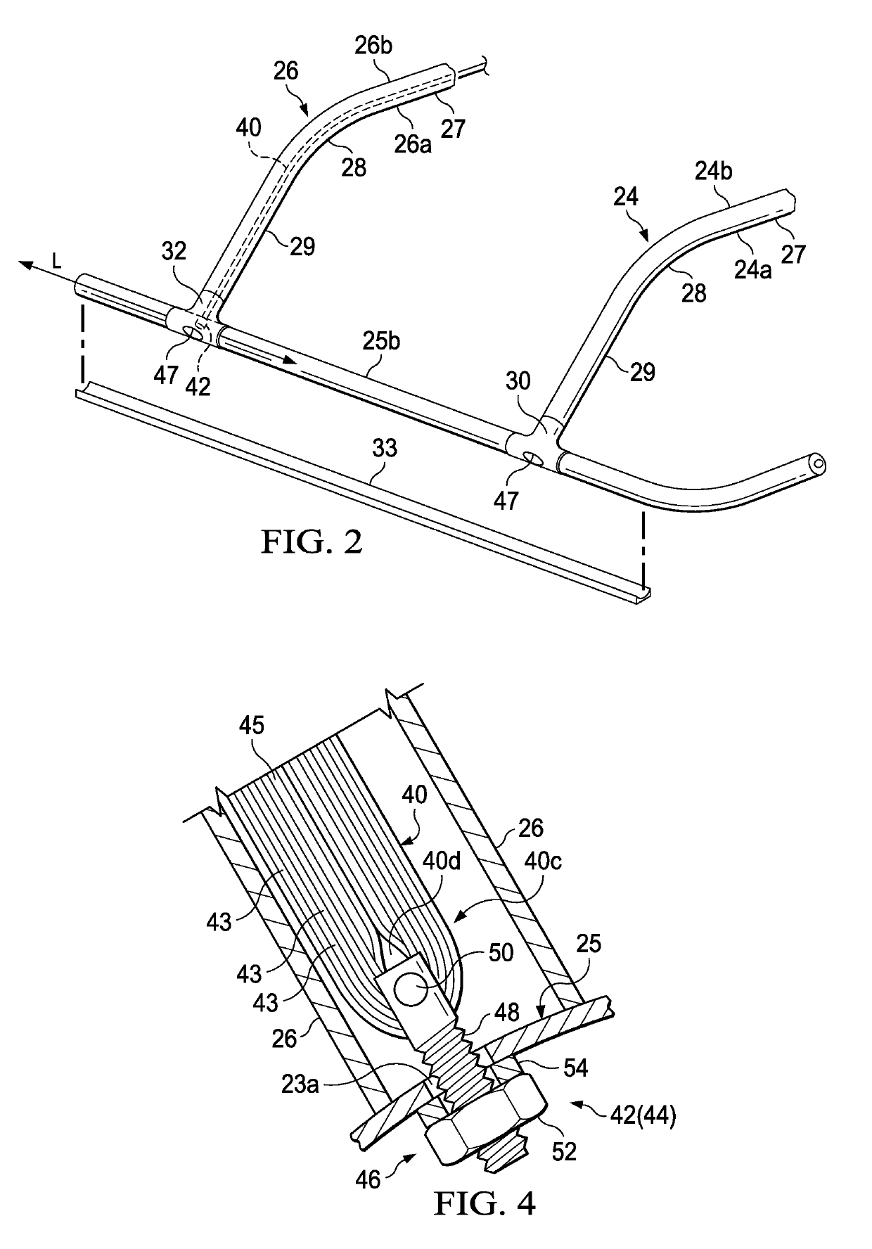
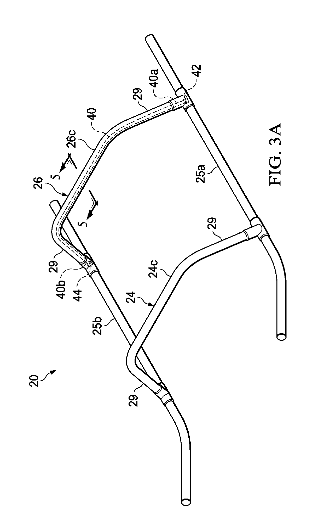
Skid landing gear assembly

a technology of landing gear and rotorcraft, which is applied in the field of aircraft, can solve the problems of cracking of the lower wall region, fatigue failure of conventional cross tubes, and significant vertical loads on the rear cross tubes, and achieve the effect of tensile stress on the tension cable member

Active Publication Date: 2019-08-15
BELL HELICOPTER TEXTRON INC
View PDF0 Cites 2 Cited by
  • Summary
  • Abstract
  • Description
  • Claims
  • Application Information

AI Technical Summary

Benefits of technology

The patent text describes a method of operating a helicopter with skid landing gear assembly connected to a fuselage. The method involves landing the helicopter on the skid landing gear assembly and using a tension cable to resist outward deflection of the assembly. The applied tension increases as outward deflection of the assembly increases, improving its service life. The technical effect is better resistance to damage and increased durability of the skid landing gear assembly.

Problems solved by technology

Conventional cross tubes are subjected to significant vertical loads and outward deflection during landing of the helicopter.
Conventional cross tubes, particularly the rear cross tubes, can suffer fatigue failure and cracking of the lower wall region as result of excessive tensile stresses experienced during numerous repeated landings of the helicopter.

Method used


Image

  • Skid landing gear assembly
  • Skid landing gear assembly
  • Skid landing gear assembly

Examples


Embodiment Construction

[0046]Illustrative embodiments of the skid landing gear assembly and methods related thereto are described below. In the interest of clarity, all features of an actual implementation may not be described in this specification. It will, of course, be appreciated that in the development of any such actual embodiment, numerous implementation-specific decisions must be made to achieve the developer's specific goals, such as compliance with system-related and business-related constraints, which will vary from one implementation to another. Moreover, it will be appreciated that such a development effort might be complex and time-consuming but would nevertheless be a routine undertaking for those of ordinary skill in the art having the benefit of this disclosure

[0047]In the specification, reference may be made to the spatial relationships between various components and to the spatial orientation of various aspects of components as the devices are depicted in the attached drawings. However,...


PUM


Abstract

An aspect provides a skid landing gear assembly including a cross member disposed between a first skid tube and a second skid tube, and a tension cable member configured to be disposed in the cross member; wherein the tension cable member resists outward deflection of at least a portion of the skid landing gear assembly when a downward load is applied to the skid landing gear assembly. In other aspects, there are methods of avoiding ground resonance in a skid landing gear assembly, methods of assembling a skid landing gear assembly, methods of operating a helicopter with a skid landing gear assembly, and methods of improving the service life of a skid landing gear assembly.

Description

BACKGROUNDTechnical Field[0001]The present disclosure relates to aircrafts, and more particularly to skid landing gear for rotorcraft.Description of Related Art[0002]Helicopters, and particularly small and medium helicopters, may be equipped with a skid type landing gear. Conventional skid landing gear systems generally include two longitudinal skid tubes for contacting the ground and two cross tubes, fore and aft, connecting the skid tubes to the body of the helicopter, although alternate designs are also possible.[0003]Skid landing gear systems are generally designed with consideration of energy absorption during hard landings, stress levels in normal landings which should be low enough to ensure a satisfactory fatigue life, and an appropriate stiffness to avoid critical ground resonance modes. Moreover, skid landing gear systems are designed to maximize fatigue life during normal rotorcraft operations.[0004]Conventional cross tubes typically have a generally circular or rectangul...

Claims


Application Information

Patent Timeline
Patent Type & Authority Applications(United States)
IPC IPC(8): B64C25/52B64F5/00
CPCB64C25/52B64F5/00B64C2025/325
Inventor SMITH, MICHAEL R.LARKIN, III, JOHN C.
Owner BELL HELICOPTER TEXTRON INC
Learn More