Fixture for a lamp, and lighting element

a technology for fixing elements and lamps, applied in the direction of vehicle spotlighting, vehicle lighting, lighting support devices, etc., can solve the problems of high installation and removal requirements, high time-consuming, and complicated installation and removal of lamps, and achieve simple contour, simple connection, and cost-effective manufacturing

Active Publication Date: 2019-07-25
SCHOTT AG
View PDF3 Cites 0 Cited by
  • Summary
  • Abstract
  • Description
  • Claims
  • Application Information

AI Technical Summary

Benefits of technology

[0055]The interface for establishing the connection is very simple and cost-effective to manufacture. Only a simple contour is required in the opening of the accommodating element, which can be produced by milling, for example. Accordingly, the fixture itself may be produced in the form of a milled part, for example made of aluminum, or as a plastic injection-molded part, with the at least one rib and the latching element formed thereon.
[0056]It is moreover particularly advantageous that no loose parts or additional fastening elements such as screws are used, which might fall down or be lost during installation or removal.

Problems solved by technology

Especially in the aviation sector, requirements are particularly high, since there is usually little space available for the lights, and moreover there exist high safety requirements, for example in terms of attachment.
Typically, such lights are mounted to the seat structure with a plurality of screws, so that installation and removal thereof is time-consuming.
In addition, the fastening by means of multiple screws is associated with a rather high expenditure of time and moreover requires the attachment of a covering for hiding the screws.
For example, a small screw that is lost during removal might cause considerable damage, for example when it falls into openings or shafts in the aircraft floor, where it may unintentionally block movements or even cause a short circuit.
Other common lamps are possible as well, of course, but there may be restrictions in terms of a desired small installation depth here.

Method used


Image

  • Fixture for a lamp, and lighting element
  • Fixture for a lamp, and lighting element
  • Fixture for a lamp, and lighting element

Examples


Embodiment Construction

[0069]For the sake of clarity, the same reference numerals in the following detailed description of preferred embodiments indicate substantially similar parts in or on these embodiments. However, for better illustration of the invention, the preferred embodiments shown in the figures are not always drawn to scale.

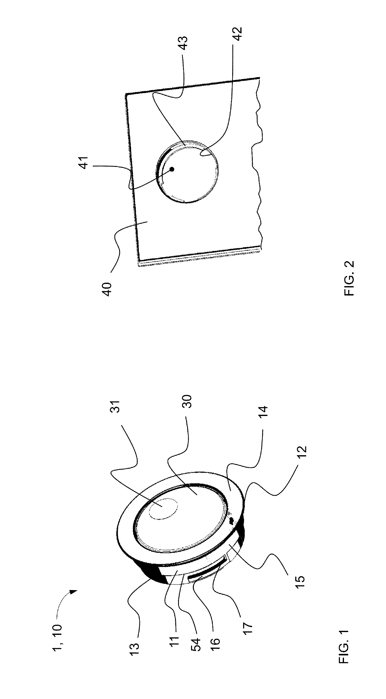
[0070]FIG. 1 is a perspective view of a lighting element 1 in a preferred embodiment comprising the fixture 10 according to the invention and a lamp 30. Lighting element 1 is designed as a reading lamp, without being limited to the illustrated exemplary embodiment.

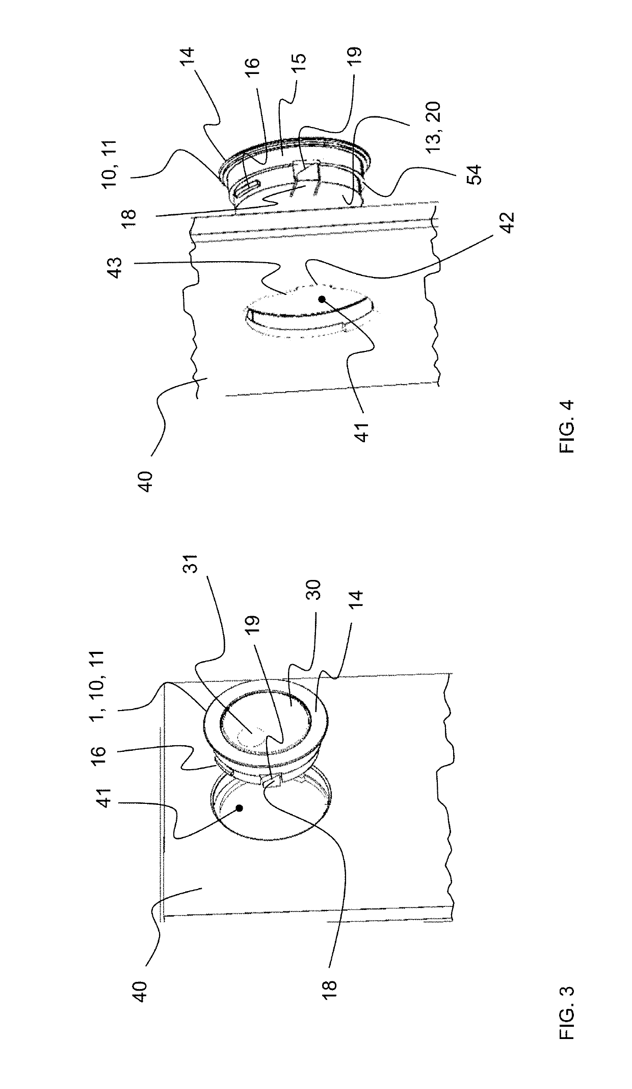
[0071]The fixture 10 is designed for being releasably fastened in an opening of an accommodating element 40 provided for this purpose, which is shown in FIG. 2, purely by way of example. FIG. 2 accordingly shows a detail of an accommodating element 40 having a circular opening 41 for receiving the lighting element 1.

[0072]Fixture 10 comprises a circular-cylindrical mounting element 11 having a lateral wall 15, a f...


PUM


Abstract

A fixture for a lamp and to a lighting element are provided that is usable as a reading light, for example in a vehicle or aircraft. The fixture is adapted to be releasably installed in an opening of an accommodating element and includes a cylindrical mounting element having a lateral wall, a front side, and an opposite rear side. The front side has an opening for receiving the lamp. The lateral wall has a radially outwardly projecting rib and a radially outwardly projecting latching element.

Description

CROSS REFERENCE TO RELATED APPLICATIONS[0001]This application claims benefit under 35 USC 119 of German Application 10 2018 101 384.1 filed Jan. 23, 2018, the entire contents of which are incorporated herein by reference.BACKGROUND1. Field of the Invention[0002]The present invention generally relates to a fixture for a lamp and to a lighting element. More particularly, the invention relates to a lighting element which can be used as a reading light, for example in a vehicle or aircraft.2. Description of Related Art[0003]The market for lighting means and consequently also that for lamps and lighting assemblies is subject to rapid technological development. Thus, there are constantly new fields of application for lighting means in their current stage of development. In this context, light emitting diodes (LEDs) are in particular worth mentioning, whose latest developments offer new fields of application, for example in the automotive or aviation sectors.[0004]Especially in the aviatio...

Claims


Application Information

Patent Timeline
Patent Type & Authority Applications(United States)
IPC IPC(8): F21V21/30
CPCF21V21/30F21V21/044F21V21/047B64D2011/0053F21V21/041B60Q3/51B60Q3/44B60Q3/76
Inventor DIETRICH, ANDREAS
Owner SCHOTT AG
Why Eureka
Try Eureka