
Surface mount security barrier

Active Publication Date: 2019-07-25
GME SPRINGS LTD
View PDF0 Cites 0 Cited by
  • Summary
  • Abstract
  • Description
  • Claims
  • Application Information

AI Technical Summary

Benefits of technology

The invention is a security barrier section that prevents vehicles from penetrating through it. It consists of cast concrete blocks with spring steel posts and second cables placed between them. The second cables are positioned lower and spaced from the spring steel posts, so in the event of an impact, the vehicle acts as an anchor and prevents the barrier section from becoming airborne. The cast concrete blocks also have fence post recesses that allow for the installation of fence panels on both sides, providing double-sided protection.

Problems solved by technology

Once a barrier becomes airborne it usually suffers catastrophic failure, has little further resistance and, as such, cannot prevent vehicular penetration.

Method used


Image

  • Surface mount security barrier
  • Surface mount security barrier
  • Surface mount security barrier

Examples


Embodiment Construction

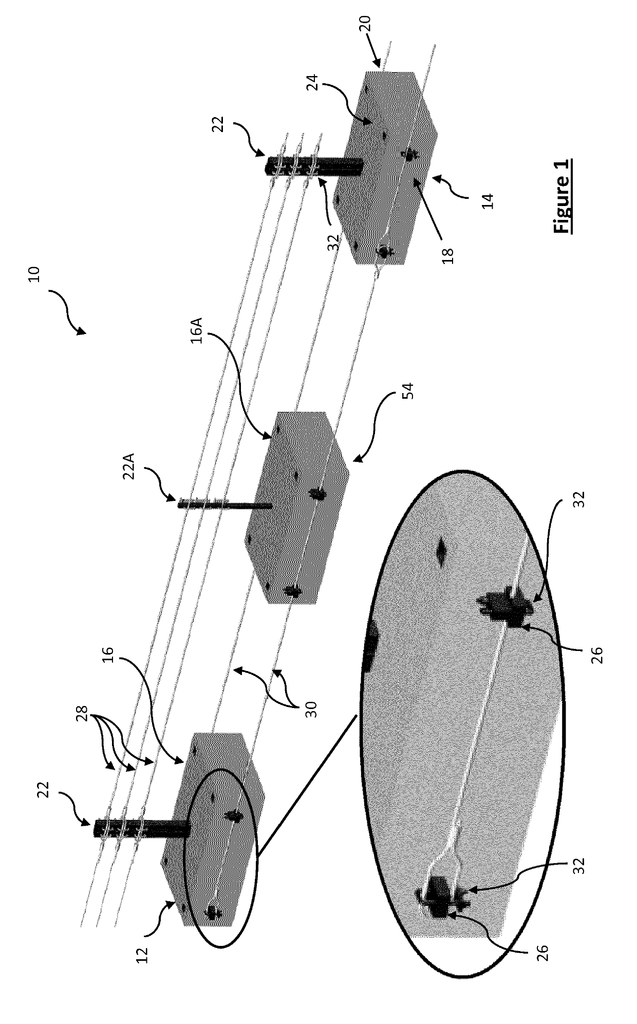
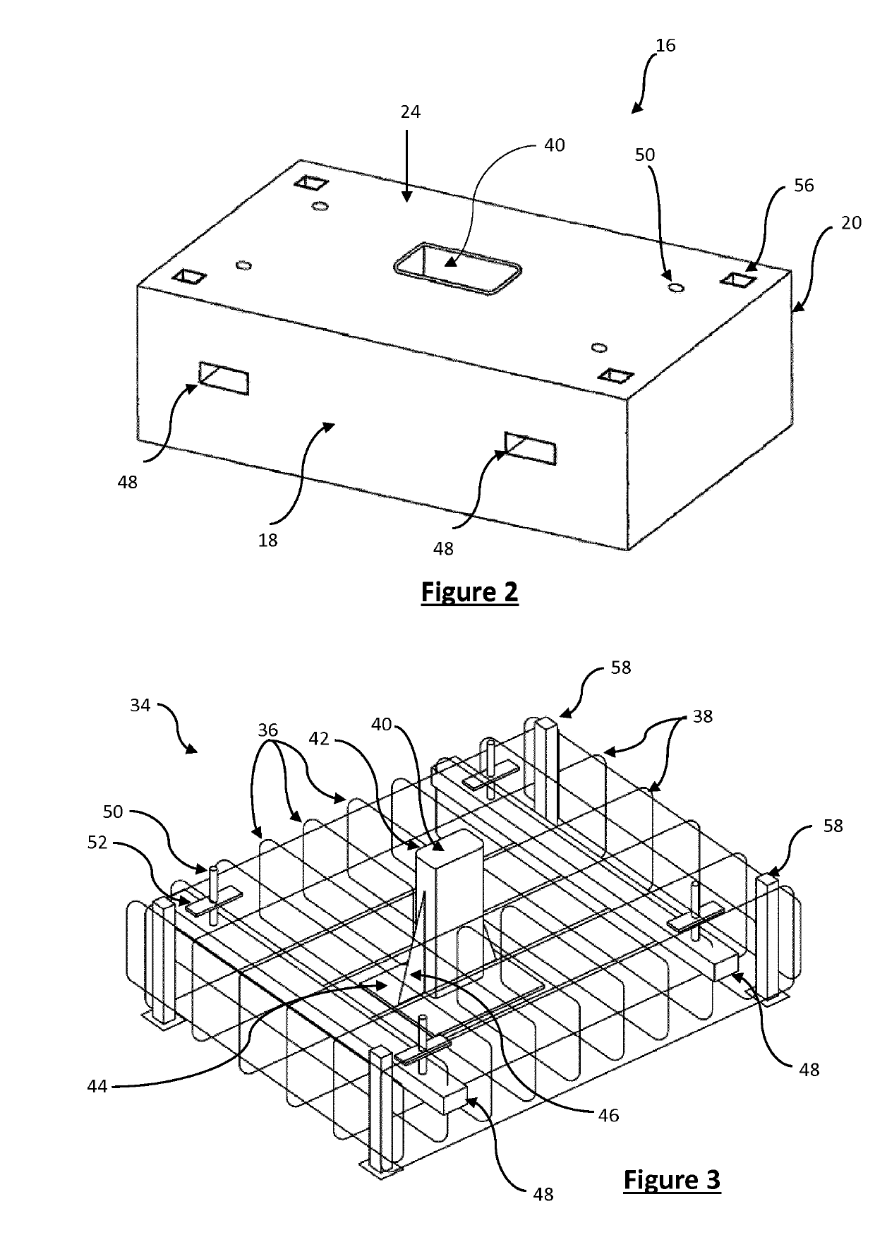
[0033]Referring to FIG. 1 a security barrier section 10 is shown. The security barrier section 10 comprises first and second barrier islands 12, 14 each of which comprise a cast concrete block 16 having a front face 18 and a rear face 20. The security barrier islands are designed to be simply placed on the surface where a security barrier is needed, i.e. they provide a surface mount security barrier that does not need to be located in an excavated trench and does not need to be attached to the surface. The concrete block 16 is described in more detail with reference to FIGS. 2 and 3 below.

[0034]A spring steel post 22 extends upwardly from a top face 24 of the cast concrete block 16 at a location between the front face and the rear face. As can be seen in the example embodiment the spring steel post 22 is located substantially in the centre of the concrete block 16. The exact location of the spring steel post 22 is not critical providing that it is spaced from either the front or the...


PUM


Abstract

The invention provides a security barrier section (10) which has first (12) and second (14) barrier islands and cables (28, 30) there between. Each barrier island comprises a cast concrete block (16) having a front face and a rear face and a spring steel post (22) extending upwardly from a top face of the cast concrete block at a location between the front face and the rear face. An attachment means (26) is located on, or extending from, at least one of the front face and the rear face. At least one first cable (28) extends between the spring steel posts (22) of said the first (12) and second (14) barrier islands and is attached thereto by cable attachments. At least one second cable (30) extends between the attachment means (26) of said first (12) and second (14) barrier islands and is also attached thereto by cable attachments. The cable attachments are configured to allow said cable to slip in said cable attachment under loading.

Description

TECHNICAL FIELD[0001]The present invention relates to a security barrier section, a security barrier and a security barrier island, in particular for use in a surface mounted security barrier to prevent vehicular penetration.BACKGROUND[0002]Security barriers, or crash barriers, the main purpose of which being to prevent the passage of vehicles, are widely known in the art and have many applications. Common applications are for bordering dangerous sections of roads, providing a central separation between lanes of traffic moving in opposite directions, and around secure areas, for example around the entrance to airports or the like.[0003]Known security barriers are generally made of metals, in particular steel, and comprise a post, which is bedded in concrete, and to which a barrier is attached. To provide the structural integrity to stop a car moving at around 40 to 50 km / h (about 25 to 30 mph), such barriers need a very deep, reinforced bedding of around a meter in depth and, for la...

Claims


Application Information

Patent Timeline
IPC IPC(8): E01F13/02E01F13/12
CPCE01F13/028E01F13/12E01F15/06E01F15/083
Inventor GERRARD
Owner GME SPRINGS LTD
Learn More