Stator for an electrical machine

a technology for electric machines and statators, applied in the direction of windings, magnetic circuit stationary parts, magnetic circuit shape/form/construction, etc., can solve the problem of increasing manufacturing costs

Active Publication Date: 2019-07-11
ROBERT BOSCH GMBH
View PDF0 Cites 2 Cited by
  • Summary
  • Abstract
  • Description
  • Claims
  • Application Information

AI Technical Summary

Benefits of technology

[0014]It is moreover advantageous if the same pitch is provided in each case between the conductor limbs connected via a conductor connection. A very uniformly constructed end winding is thus produced on the one end face of the stator.

Problems solved by technology

These special connectors increase the manufacturing costs.

Method used


Image

  • Stator for an electrical machine
  • Stator for an electrical machine
  • Stator for an electrical machine

Examples


Embodiment Construction

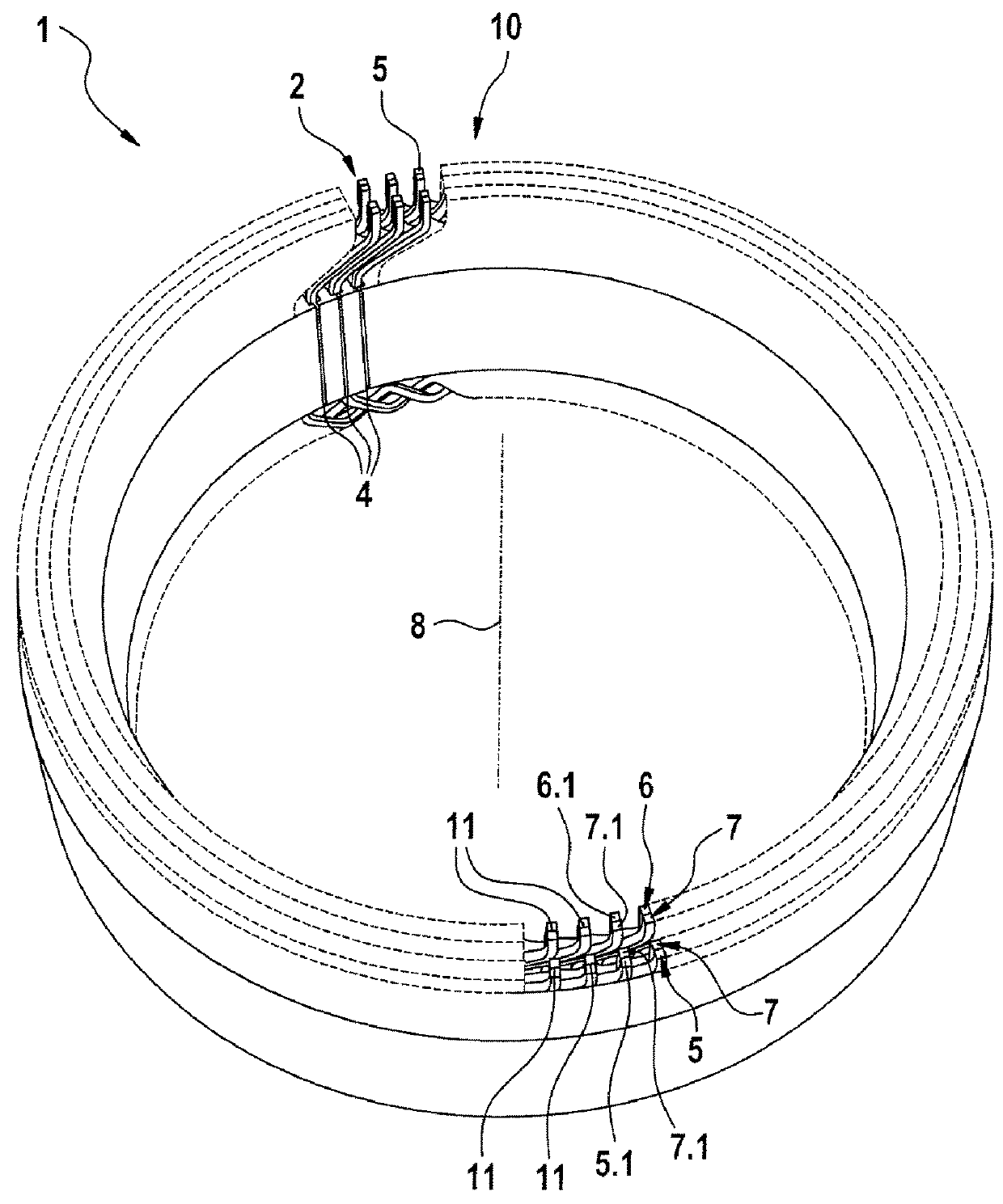
[0025]FIG. 1 shows a three-dimensional view of an end face of an inventive stator having, for example, four conductors for each slot.

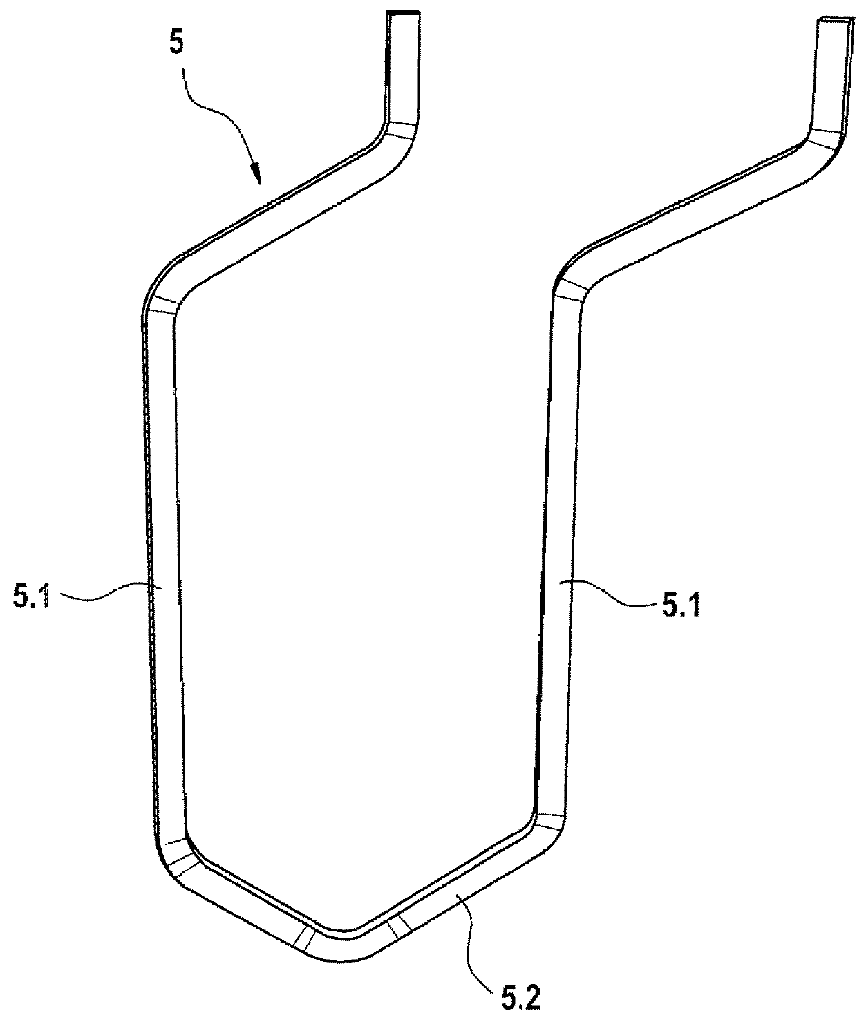
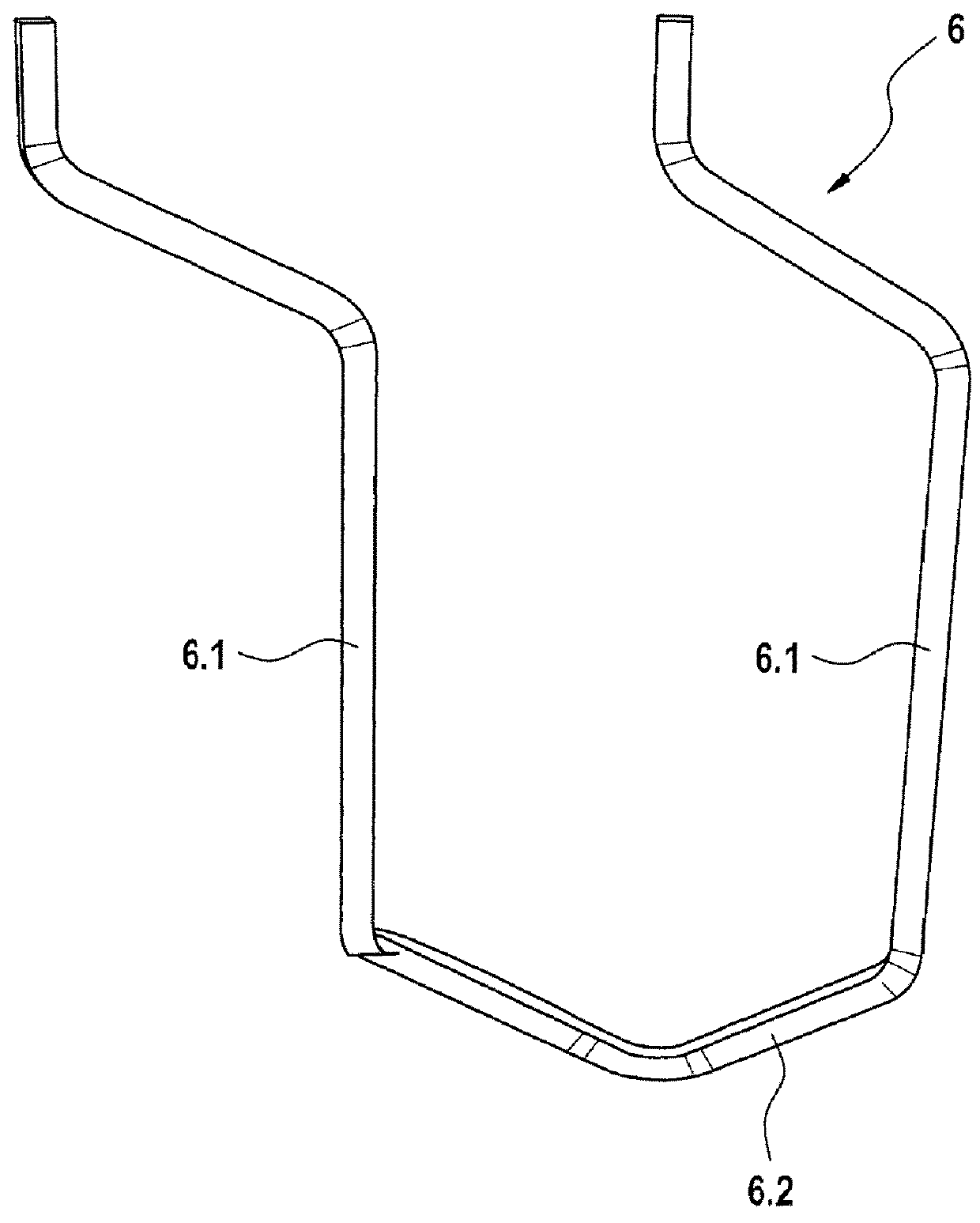
[0026]The stator 1 of an electric machine has a polyphase winding 2, which is formed as a plug winding, whereof individual winding strands 3 extend through slots 4 of the stator 1 and which comprises a plurality of different conductor elements 5, 6, 7 electrically connected in series. Each winding strand 3 of the polyphase winding 2 is associated with one of the electrical phases u,v,w of the electric machine. In this case, each winding strand 3 can be divided into a plurality of parallel-extending, electrically mutually insulated sub-strands or winding branches. The polyphase winding 2 is, for example, a three-phase or six-phase winding. At least some, in particular a plurality, of these conductor elements 5, 6, 7 are formed according to FIG. 2, FIG. 3 and FIG. 4.

[0027]FIG. 2 shows a first conductor element 5, FIG. 3 a second conductor element 6 and F...


PUM


Abstract

Stators for an electrical machine which are fitted with a polyphase winding which is in the form of a plug-type winding and the winding sections of which run through slots of the stator and comprise a plurality of different conductor elements are already known. At least some of the said conductor elements have in each case two conductor limbs and in each case one connecting conductor which connects the two conductor limbs, wherein an even number of n conductor limbs is arranged one above the other in the radial direction with respect to a stator axis in each slot. Each conductor limb of one of the conductor elements is provided in its slot in a specific position with respect to a slot base of the slot. These polyphase windings comprise a comparatively large number of different conductor elements, in particular so-called special conductors which differ from the standard conductor elements. These special conductors increase the manufacturing costs. In the case of the stator according to the invention, a few different conductor elements are provided for the polyphase winding. According to the invention, it is provided that the lower conductor elements (5) each have conductor limbs (5.1) which are situated in the same position and the upper conductor elements (6) each have conductor limbs (6.1) which are situated in the same position, wherein the step width of the lower conductor elements (5) in relation to the step width of the upper conductor elements (6) differs by the value of one, in particular is greater by the value of one.

Description

BACKGROUND OF THE INVENTION[0001]The invention starts with a stator for an electric machine.[0002]A stator for an electric machine is already known from JP2014007795 A or DE 103 31 841 A1, which supports a polyphase winding which is formed as a plug winding and whereof the winding strands extend through slots of the stator and comprise a plurality of different conductor elements. At least some of these conductor elements each have two conductor limbs and each have a connecting conductor connecting the two conductor limbs, wherein, in each slot, an even number of n conductor limbs is arranged one above another in the radial direction with respect to a stator axis. Each conductor limb of one of the conductor elements is provided in its slot in a specific layer with respect to a slot base of the slot. The conductor elements lie in the slots in such a way that all connecting conductors lie on the same end face of the stator. Moreover, the ends of the conductor limbs which are remote fro...

Claims


Application Information

Patent Timeline
Patent Type & Authority Applications(United States)
IPC IPC(8): H02K3/28H02K1/16H02K3/12
CPCH02K3/28H02K1/16H02K3/12
Inventor RIEDL, JOHANNESKUDLEK, ALEXANDERFRUEHAUF, PATRICK
Owner ROBERT BOSCH GMBH
Why Eureka
Try Eureka