
Control Apparatus, Control Method, and Control System for Electric Vehicle

a control apparatus and electric vehicle technology, applied in the direction of electric devices, brake systems, vehicle sub-unit features, etc., can solve the problem of unnecessary torque fluctuation on the rear wheels, and achieve the effect of preventing or reducing unnecessary torque fluctuation on the wheels not targeted for slip control

Active Publication Date: 2019-06-27
HITACHI ASTEMO LTD
View PDF0 Cites 4 Cited by
  • Summary
  • Abstract
  • Description
  • Claims
  • Application Information

AI Technical Summary

Benefits of technology

The invention prevents or reduces the fluctuation of torque on a wheel that is not intended for control.

Problems solved by technology

However, the above-described conventional technique raises a problem of occurrence of an unnecessary torque fluctuation on the rear wheels because a limit value of the torque to be output to the rear wheels is constantly updated according to a change in the torque to be output to the front wheels.

Method used


Image

  • Control Apparatus, Control Method, and Control System  for Electric Vehicle
  • Control Apparatus, Control Method, and Control System  for Electric Vehicle
  • Control Apparatus, Control Method, and Control System  for Electric Vehicle

Examples


first embodiment

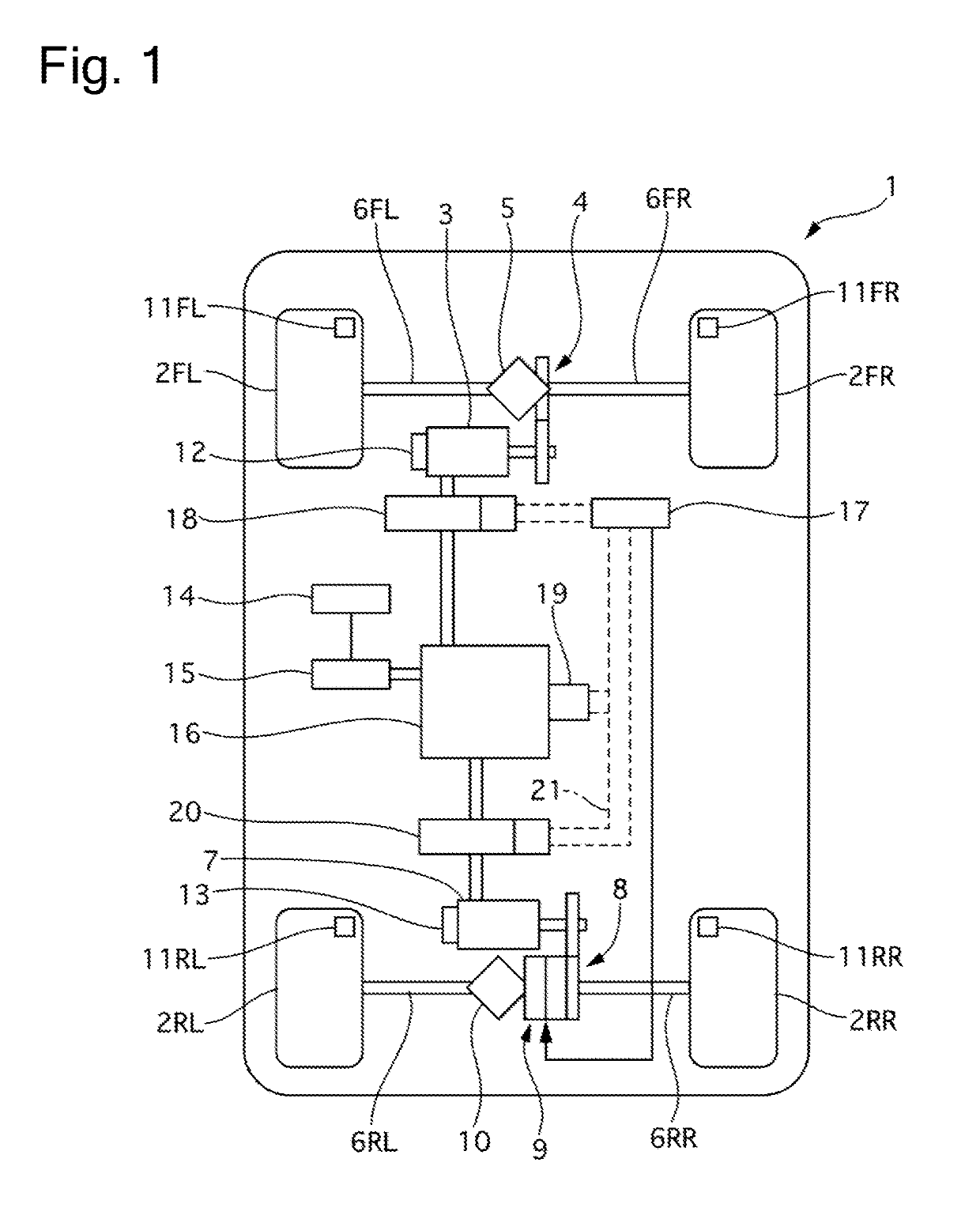
[0017]FIG. 1 illustrates a configuration of a control system of an electric vehicle according to a first embodiment.

[0018]An electric vehicle 1 includes a front motor 3, which outputs a torque to front-side wheels (hereinafter also referred to as front wheels) 2FL and 2FR. Power is transmitted between the front motor 3 and the front wheels 2FL and 2FR via a speed reducer 4, a differential 5, and front axles 6FL and 6FR. The electric vehicle 1 includes a rear motor 7, which outputs a torque to rear-side wheels (hereinafter also referred to as rear wheels) 2RL and 2Rr. Power is transmitted between the rear motor 7 and the rear wheels 2RL and 2RR via a speed reducer 8, a dog clutch 9, a differential 10, and rear axles 6RL and 6RR. When the dog clutch 9 is connected, the power is transmitted between the rear motor 7 and the rear wheels 2RL and 2RR. On the other hand, when the dog clutch 9 is released, the power is not transmitted between the rear motor 7 and the rear wheels 2RL and 2RR....


PUM


Abstract

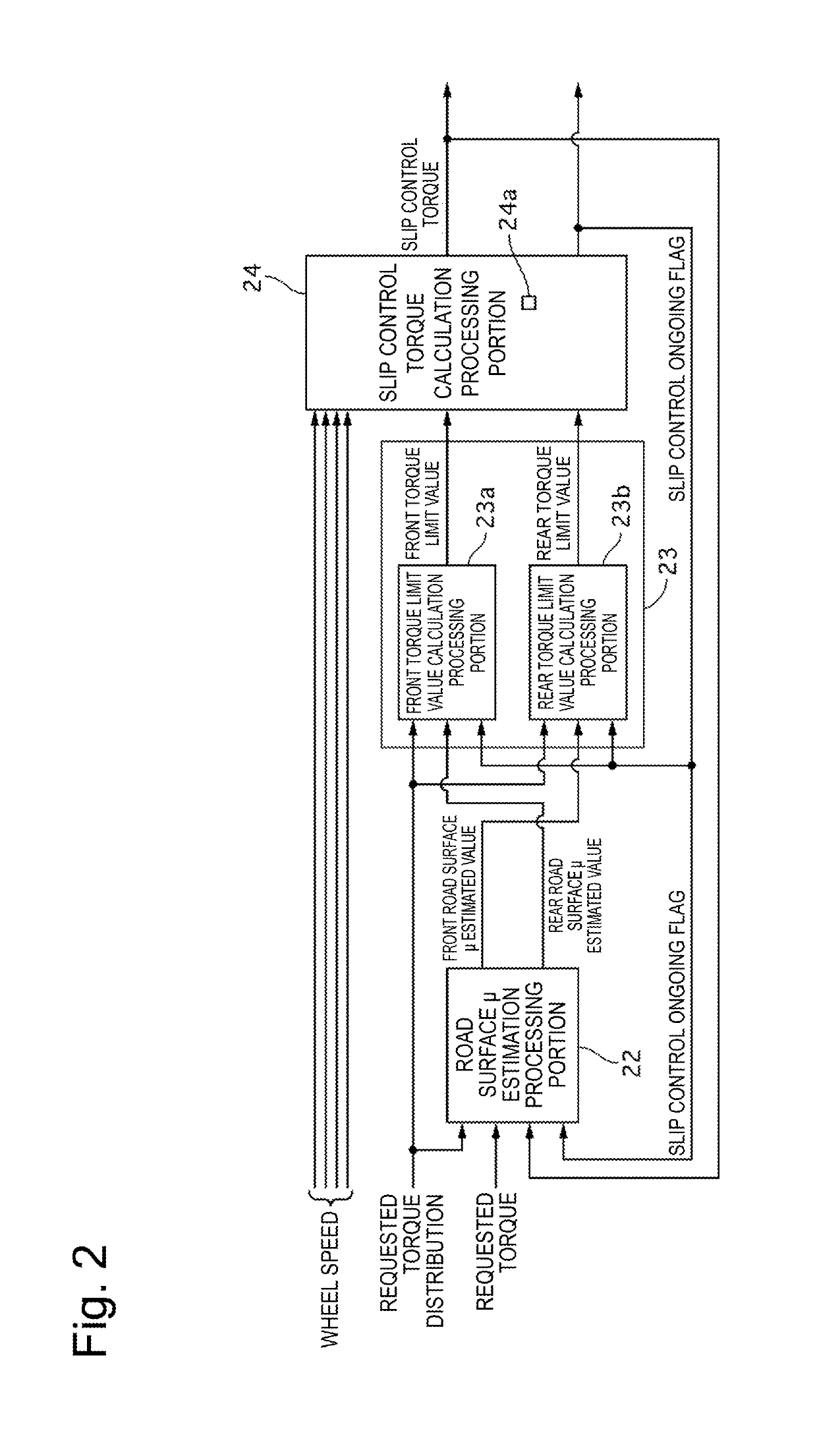
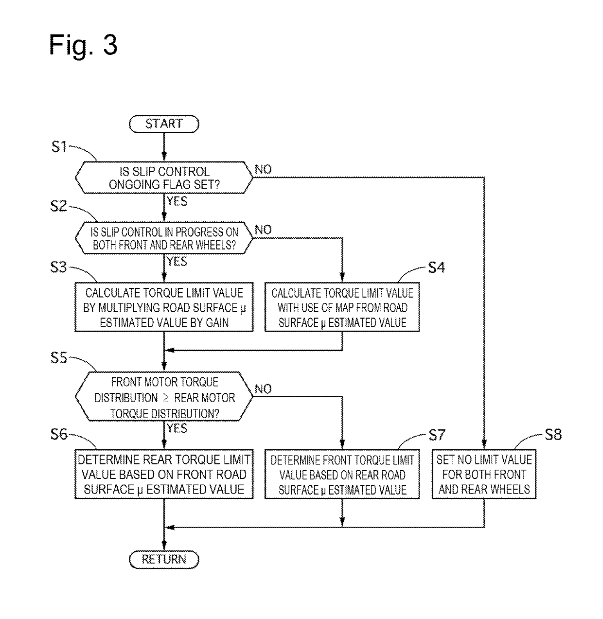
Provided is a control apparatus, a control method, and a control system for an electric vehicle that can prevent or reduce an unnecessary torque fluctuation on a wheel not targeted for slip control. A control apparatus for an electric vehicle limits a torque to be output to a non-target wheel according to a torque output to a target wheel after target wheel slip control is started, and updates a limit value of the torque to be output to the non-target wheel when a fluctuation range of the torque output to the target wheel falls within a predetermined range during the limitation.

Description

TECHNICAL FIELD[0001]The present invention relates to a control apparatus, a control method, and a control system for an electric vehicle.BACKGROUND ART[0002]Conventionally, there has been known the following technique. A control apparatus for an electric vehicle including an electric motor for front wheels and an electric motor for rear wheels eliminates or reduces a slip of the front wheels, and limits a torque to be output to the rear wheels according to a torque to be output to the front wheels, when the front wheels have slipped during four-wheel drive running (for example, PTL 1).CITATION LISTPatent Literature[0003][PTL 1] Japanese Patent Application Public Disclosure No. 2005-170086SUMMARY OF INVENTION[0004]However, the above-described conventional technique raises a problem of occurrence of an unnecessary torque fluctuation on the rear wheels because a limit value of the torque to be output to the rear wheels is constantly updated according to a change in the torque to be ou...

Claims


Application Information

Patent Timeline
Patent Type & Authority Applications(United States)
IPC IPC(8): B60L15/20B60K17/356B60K23/08
CPCB60L15/20B60K17/356B60K23/0808B60K6/52B60L3/106B60T8/175B60L2220/42B60L2240/423B60L2240/465B60L2260/28B60T2210/12B60W2720/403B60Y2400/82B60T2270/20B60Y2300/18175B60T2270/202B60L2240/647Y02T90/16Y02T10/62Y02T10/64Y02T10/72B60T8/1769B60T8/1764B60T8/1766
Inventor KANEKO, SATOSHISUZUKI, KEISUKE
Owner HITACHI ASTEMO LTD
Learn More