Closing-edge safety device with prechamber

Active Publication Date: 2019-06-06
HAAKE ANDRE +2
View PDF9 Cites 0 Cited by
  • Summary
  • Abstract
  • Description
  • Claims
  • Application Information

AI Technical Summary

Benefits of technology

The invention is about a safety device used in electrical switches that prevents accidental contact and ensures proper functioning. The device has switch nubs that are enclosed in a prechamber, which makes the surface of the switch smooth and aesthetically pleasing. The nubs are protected against external influences, such as abrasion or moisture, which can damage them and reduce their lifespan. A guide element extending the length of the prechamber ensures that the positions of the nubs cannot shift away from their desired locations. The guide element and the nubs can be fixed in position using potting or grouting compound or by clamping or gluing them to the prechamber. This ensures that the safety device is reliable and durable for a long period of use.

Problems solved by technology

When the safety device encounters an obstacle, the obstacle causes the housing to deform, thereby pressing the actuator against the switch chamber, which in turn deforms and causes the switch elements of the switching strip to pull apart or be displaced, thereby interrupting the flow of electricy through the switching strip, which interruption triggers the safety response.
The switch nub is a spatially limited device, but even when the closing edge safety device comes into contact with a large-area obstacle, such as a wall surface, floor surface, or the like, the pressure that is applied to this spatially limited device is transmitted to the switch chamber, which, as described above, results in a triggering of the desired safety response.

Method used


Image

  • Closing-edge safety device with prechamber
  • Closing-edge safety device with prechamber
  • Closing-edge safety device with prechamber

Examples


first embodiment

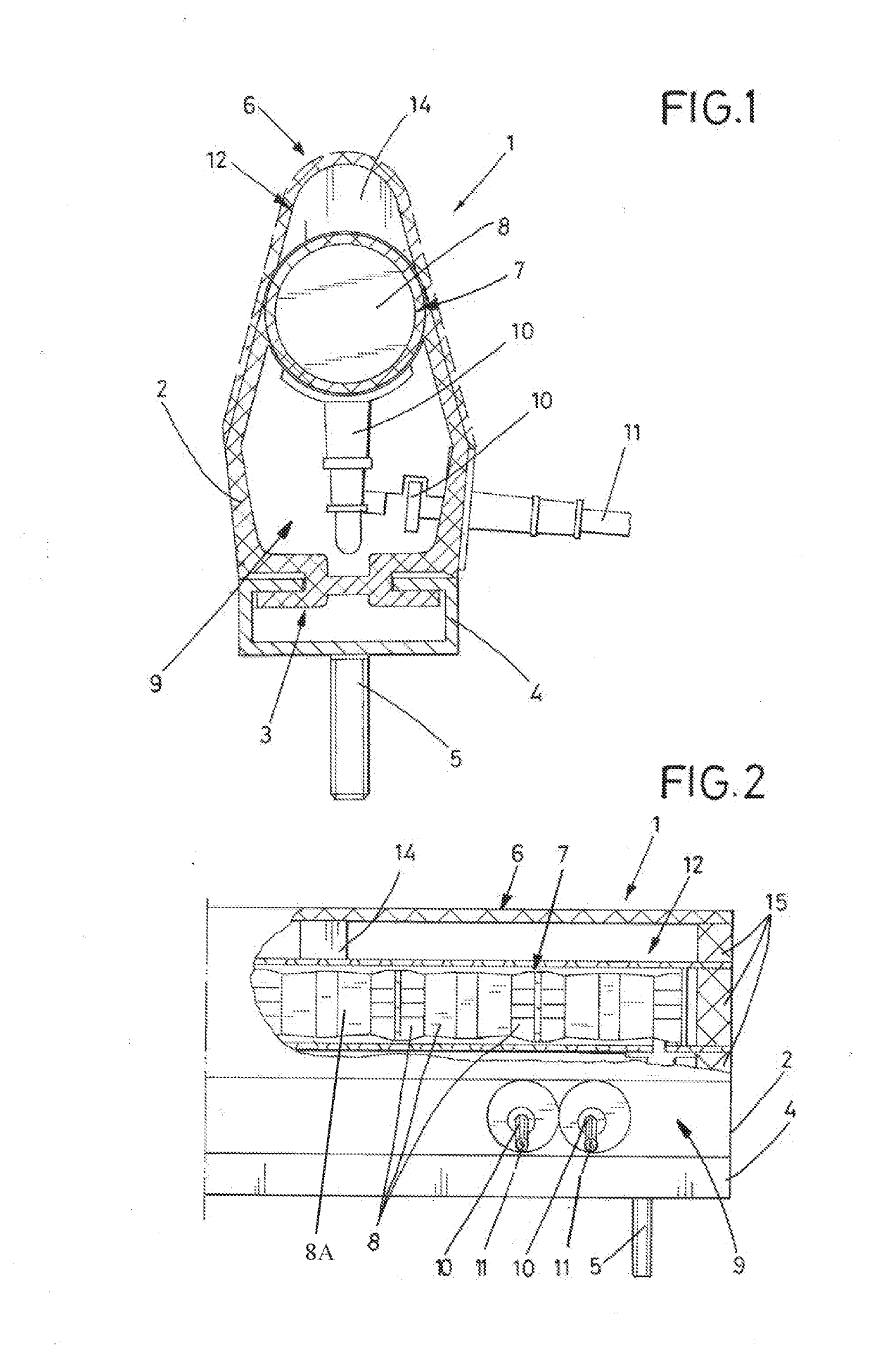
[0029]FIG. 1 illustrates a closing edge safety device 1 according to the invention that comprises a body or housing that is a profile element 2 that encloses a switch chamber 7 that contains a switching strip 8A and a cable 11 that supplies the strip 8A with electrical current, and a prechamber 12 that contains a switching nub 14. The profile element 2 is made of an elastomeric material and has a first side or mounting side 3 and a second side or leading edge 6. The closing edge safety device 1 is conventionally fastened to the equipment or device that requires safeguarding, i.e., a safety stop, by fastening the mounting side 3 to a metal rail 4 that is then mounted along the surface of the equipment or device that requires safeguarding. Fasteners 5, such as bolts, are conventionally used to fasten the closing edge safety device 1 to the equipment. The leading edge 6 of the safety device 1 is the portion of the closing edge safety device 1 that is designed and mounted so as to be th...

third embodiment

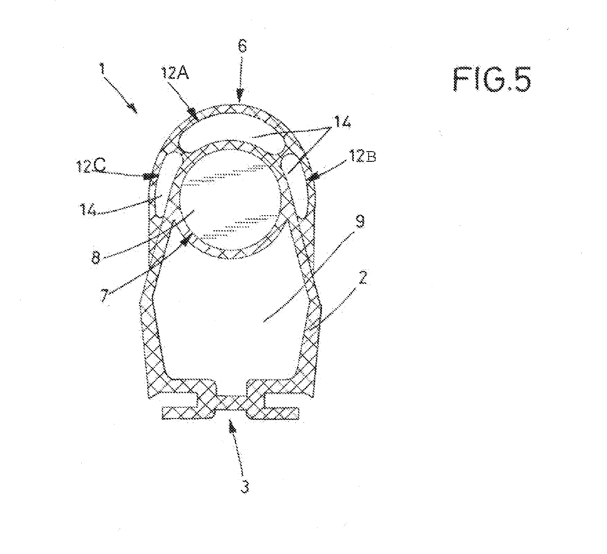
[0036]FIG. 5 illustrates the closing edge safety device 1 according to the invention, in which the prechamber 12 includes a plurality of such prechambers 12. In the embodiment shown, three prechambers 12 are provided in the area at the leading edge 6 and laterally on both sides of this leading edge. A middle prechamber 12A is directly aligned between the leading edge 6 and an upper portion of the switch chamber 7. Lateral prechambers 12B and 12C are provided on each side between the profile element 2 and an upper circumference of the switch chamber 7. All three prechambers 12 extend substantially the length of the closing edge safety device 1 and switching nubs 14 may be provided in all three prechambers. Overall, the prechambers 12A, B, and C and their switching nubs 14 in this embodiment surround more than half the circumference of the switch chamber 7. This increases the response sensitivity of the closing edge safety device 1 because the switching operation is triggered upon con...


PUM


Abstract

A closing edge safety device that triggers a safety response upon contact with an obstacle. The body of the safety device is an elastically deformable profile element that encloses a switch chamber containing a switching strip that carries an electrical current. A prechamber with a switching nub is placed at the leading edge of the safety device, in front of the switch chamber. When an external force is applied to the leading edge of the safety device, the switching nub transmits the force to the switch chamber, which also deforms, causing an interruption in the electrical current on the switching strip, thereby triggering the desired safety response of the closing edge safety device. The closing edge safety device provides improved response to large-area as well as small-area contact with an obstacle and is also suitable for use as a limit switch.

Description

BACKGROUND INFORMATIONField of the Invention[0001]The invention relates to a closing edge safety device that interrupts flow of electrical current on a switching strip upon contact with an obstacle, thereby triggering the desired safety response of the closing edge safety device.Discussion of Prior Art[0002]German Utility Model DE 299 05 816 U1A discloses a generic closing edge safety device. The safety switching strip has a plurality of contact elements, whereby the contact between the contact elements is interrupted when the switching strip undergoes a locally limited deformation. The elastically deformable profile element that houses the switching strip provides a robust, long-lasting protection for the switching strip and, due to its elastic deformability, enables the desired safety response to be triggered when the current flow on the switching strip is interrupted as a result of contact with an obstacle, yet also allows the profile element to return to its original state after...

Claims


Application Information

Patent Timeline
IPC IPC(8): H01H3/16E05F15/44
CPCH01H3/161E05F15/44H01H2003/165H01H2225/012H01H2221/05H01H3/142
Inventor HAAKE, ANDREHAAKE, OLIVERHAAKE, PATRICK
Owner HAAKE ANDRE
Why Eureka
Try Eureka