
Eye-safe laser-based lighting

a laser-based lighting and laser-based technology, applied in the field of laser-based light sources, can solve the problems of annoying speckles, low illumination efficiency of laser-based light, etc., and achieve the effect of reliable eye safety

Pending Publication Date: 2019-05-30
SIGNIFY HLDG BV
View PDF0 Cites 1 Cited by
  • Summary
  • Abstract
  • Description
  • Claims
  • Application Information

AI Technical Summary

Benefits of technology

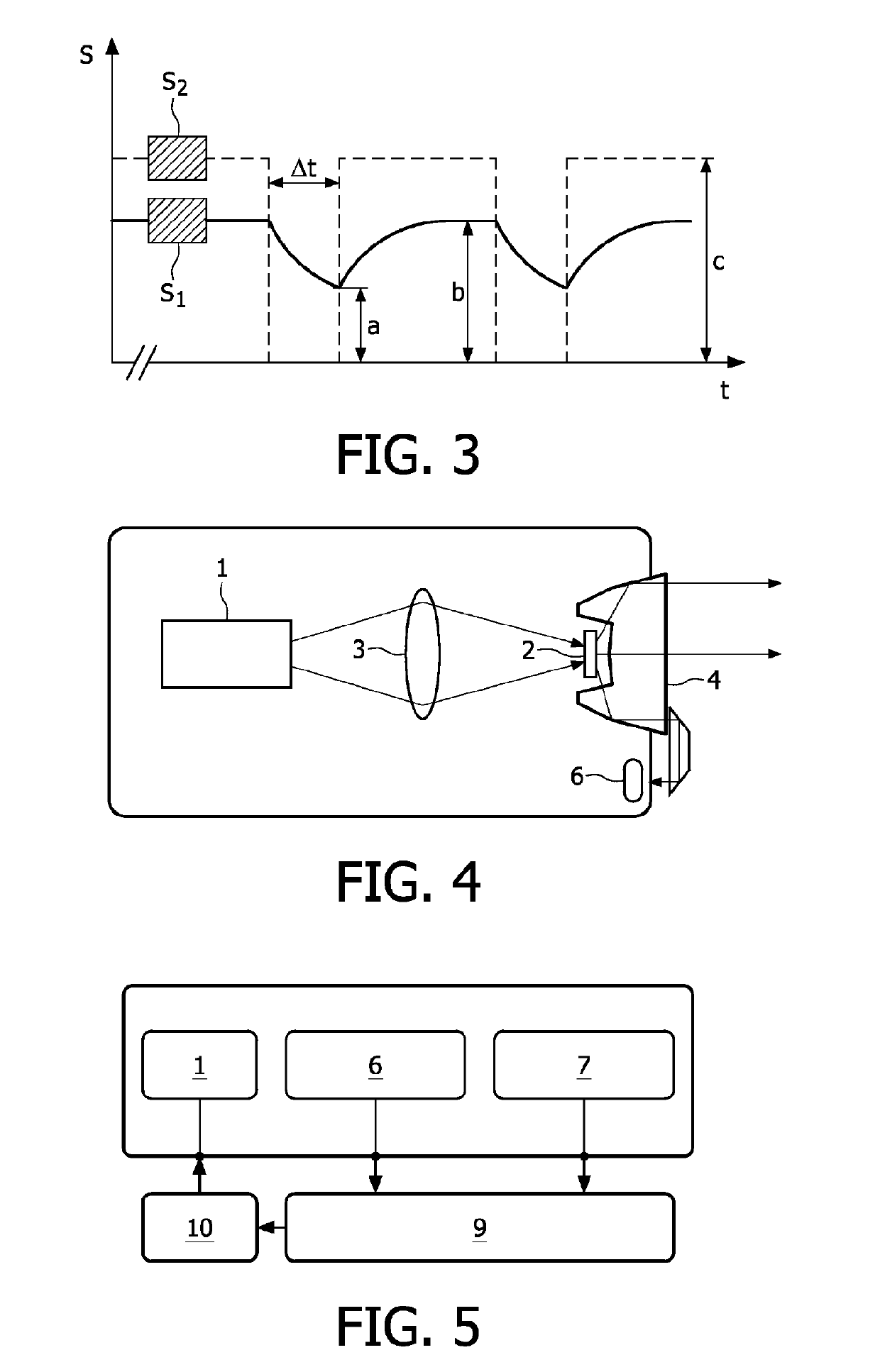
The invention provides a laser-based light source and a method of operating it that ensures reliable eye-safety in an easy way. The light source can use different types of light-conversion devices, such as phosphors or scattering devices, and sensors can be used for measuring the laser output or converted light. The ratio between the laser-output signal and the converted-light signal can be used to determine the safe-to-operate parameter, which can be used for shutting down or warning the user if the light source is not safe to operate. The light output can be stabilized based on the determined laser-output signal or converted-light signal, and a closed control loop can be used for this purpose.

Problems solved by technology

Laser light by itself will not be of much use for illumination since the laser beam is too bright to be eye-safe, too monochromatic for faithful colour reproduction and will result in annoying speckle due to its coherence.
However, one critical issue with laser-based lighting is the fact that the light source should adhere to strict legislation and be eye-safe under all circumstances, even when tampered with.

Method used


Image

  • Eye-safe laser-based lighting
  • Eye-safe laser-based lighting

Examples


Embodiment Construction

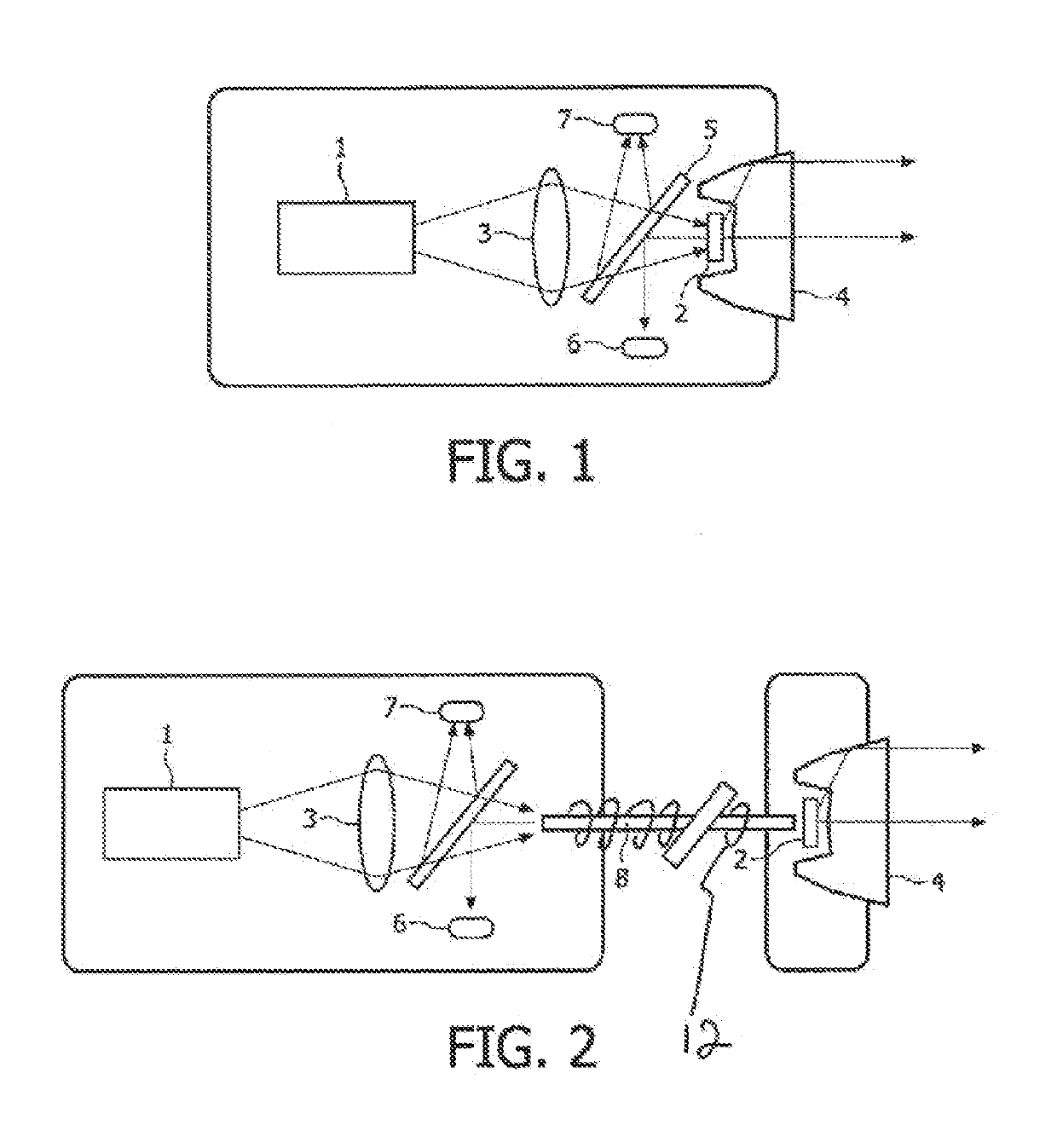
[0044]A first embodiment according to the invention is schematically depicted in FIG. 1. Laser light is generated by a laser device 1, i.e. a diode laser, e.g. in an edge-emitting geometry or a vertical-cavity surface-emitting geometry (VCSEL). This laser light is directed via optics 3 to a volume of phosphorous material of a light-conversion device 2 which is in a powderous or crystalline, preferably polycrystalline, state. The laser device 1 emits blue light, preferably around 445 nm. The light-conversion device 2 converts the blue laser light into broadband yellow light. The combination of this yellow light and the remainder of the blue light results in white light. The white light generated in this way is shaped into a beam by means of collimating optics 4.

[0045]Some of the light generated by the light-conversion device 2 as well as some of the laser light is redirected towards the laser device 1. A beam splitter 5 at an angle of 45° is used to direct a fraction of this light to...


PUM


Abstract

A laser-based light source includes a laser device configured to generate laser light of a predetermined laser wavelength and emit this laser light as a laser beam. A light-conversion device is configured to convert at least part of the laser light into converted light and a laser-output sensor is configured to determine a laser-output signal proportional to the output of laser light emitted by the laser device. Further, a converted-light sensor is configured to determine a converted-light signal proportional to the output of converted light emitted by the light-conversion device. A controller is configured to receive the laser-output signal and the converted-light signal, to determine a safe-to-operate parameter, based on the laser-output signal and the converted-light signal, and to control the operation of the laser-based light source based on a comparison of the safe-to-operate parameter with a at least one predefined threshold.

Description

CROSS-REFERENCE TO RELATED APPLICATIONS[0001]This application is a divisional of pending U.S. patent application Ser. No. 14 / 848,306, filed Sep. 8, 2015, which is a divisional of prior U.S. patent application Ser. No. 13 / 001,858, filed Dec. 29, 2010, which is a national application of PCT Application No. PCT / IB2009 / 052837, filed Jun. 30, 2009 and claims the benefit of European Patent Application No. 08104656.7, filed Jul. 7, 2008, the entire contents of each of which are incorporated herein by reference thereto.FIELD OF THE INVENTION[0002]The invention relates to the field of a laser-based light source and a method of operating the same, and especially to eye-safe laser-based lighting.BACKGROUND OF THE INVENTION[0003]During the last decades, thanks to the advances of semiconductor technology, LEDs (Light Emitting Diodes) have become more and more important in lighting applications. Technological breakthroughs in high-power LEDs have opened the door to new lighting concepts driven by...

Claims


Application Information

Patent Timeline
Patent Type & Authority Applications(United States)
IPC IPC(8): H01S5/0683H01S5/068F21K9/64H01S5/00F21V23/04
CPCH01S5/0683H01S5/06808H01S5/06825F21K9/64H01S5/005F21V23/0457F21Y2115/30F21V25/02F21V25/00F21S41/16F21S45/70H01S5/0087H01S5/0078
Inventor KRIJN, MARCELLINUS PETRUS CAROLUS MICHAELJAK, MARTIN JACOBUS JOHAN
Owner SIGNIFY HLDG BV
Learn More