


Quick Research
Generate reliable direction feasibility study reports for your R&D in just a few steps.

Technical Q&A
Discover and master advanced knowledge NOW. Basics, ideas, possibilities, all at once.

Find Solutions
As an expert in R&D theories, this can generate solutions to your technical problems instantly.

Evaluate Feasibility
Analyze your overall solution with one click, know your potential R&D risks in advance.

Monitor Landscape
Get weekly tech updates, stay abreast of the latest tech innovations and key insights.
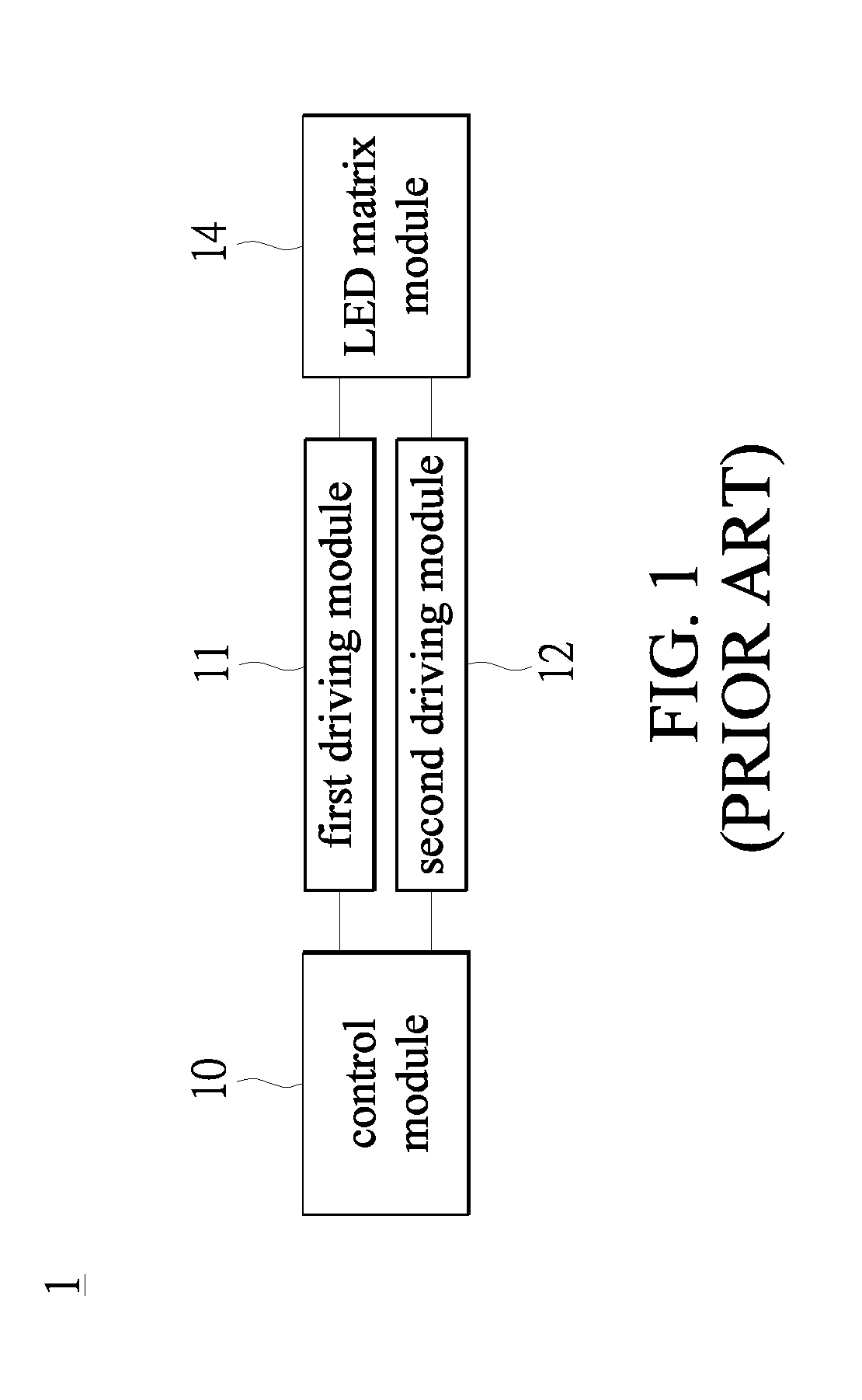
Light emitting diode driving circuit and light emitting diode display device
a technology of light-emitting diodes and driving circuits, applied in the direction of instruments, static indicating devices, etc., can solve the problems of increasing the cost of mosfets, the control method for led display devices needs to be improved. , to achieve the effect of reducing the degree of complexity of the control method, reducing the cost, and simplifying the circuit layou
- Summary
- Abstract
- Description
- Claims
- Application Information
AI Technical Summary
Benefits of technology
Problems solved by technology
Method used
Image

Examples
Embodiment Construction
[0023]The aforementioned illustrations and following detailed description are exemplary for the purpose of further explaining the scope of the present disclosure. Other objectives and advantages related to the present disclosure will be illustrated in the following description and appended drawings.
An Embodiment for an LED Display Device According to the Present Disclosure
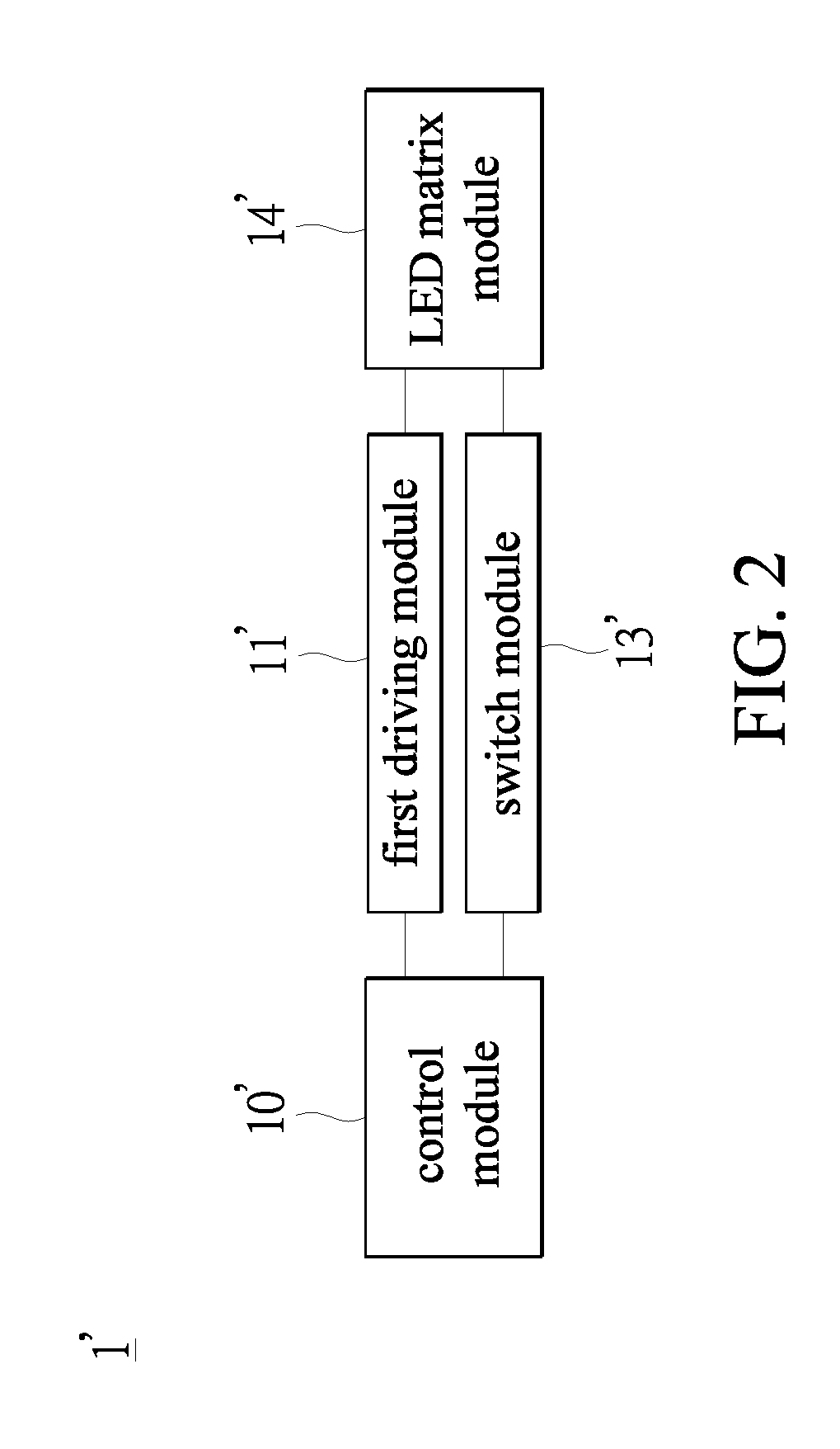
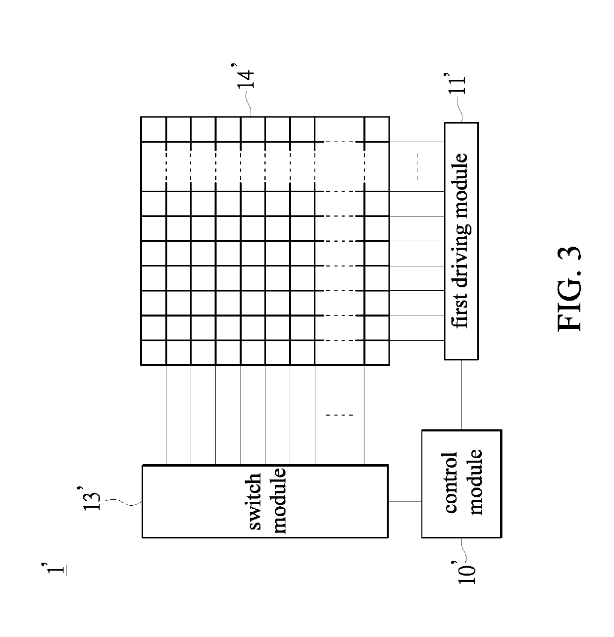
[0024]Reference is made to FIGS. 2-4, where FIG. 2 is a schematic view illustrating an LED display device according to an embodiment of the present disclosure, FIG. 3 is another schematic view illustrating the LED display device according to an embodiment of the present disclosure and FIG. 4 is another schematic view illustrating the LED display device according to an embodiment of the present disclosure.
[0025]The LED display device 1′ includes a control module 10′, a first driving module 11′, a switch module 13′ and an LED matrix module 14′. The control module 10′, the first driving module 11′ and the switch modul...
PUM
 Abstract
Description
Claims
Application Information
 - R&D Engineer
- R&D Manager
- IP Professional
- Industry Leading Data Capabilities
- Powerful AI technology
- Patent DNA Extraction
Browse by: Latest US Patents, China's latest patents, Technical Efficacy Thesaurus, Application Domain, Technology Topic, Popular Technical Reports.
© 2024 PatSnap. All rights reserved.Legal|Privacy policy|Modern Slavery Act Transparency Statement|Sitemap|About US| Contact US: help@patsnap.com