Eureka AIR delivers breakthrough ideas for toughest innovation challenges, trusted by R&D personnel around the world.

Battery state estimation method and battery state estimation device

a battery state and estimation method technology, applied in battery/fuel cell control arrangement, secondary cell servicing/maintenance, instruments, etc., can solve the problem of requiring an enormous amount of processing tim

Inactive Publication Date: 2019-04-18
HONDA MOTOR CO LTD
View PDF0 Cites 11 Cited by
  • Summary
  • Abstract
  • Description
  • Claims
  • Application Information

AI Technical Summary

Benefits of technology

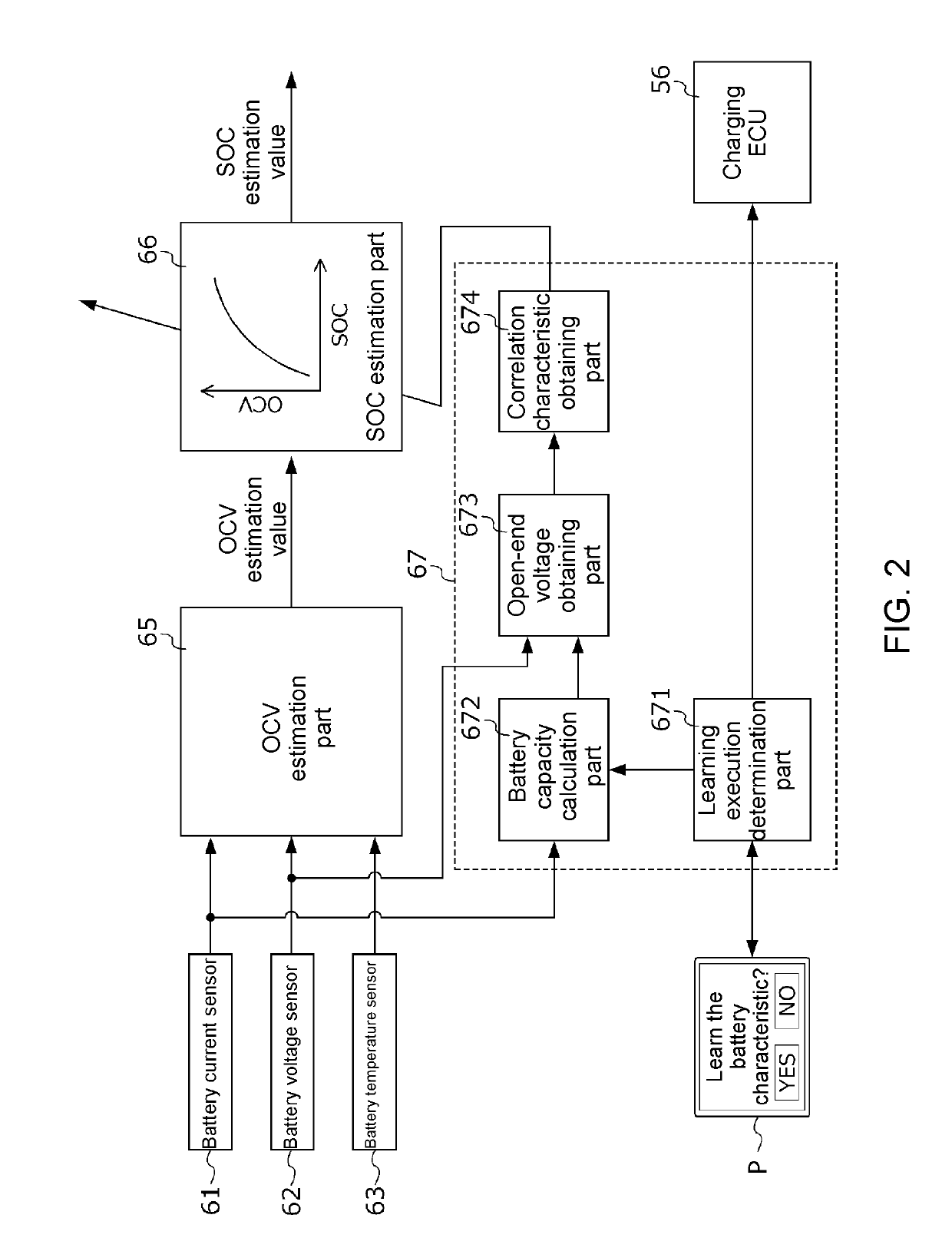
The present patent discloses a battery state estimation method for a movable body utilizing a correlation characteristic between the charging rate and the open-end voltage of the battery. The method includes steps of connecting the battery to a power source, discharging the battery to a lower-limit charge state, measuring the open-end voltage at multiple measuring points, recharging the battery from the lower-limit charge state to the full charge state, and obtaining the correlation characteristic of the battery based on charging rate and open-end voltage. The method can be performed during the battery's downtime, efficiently utilizing the battery's power. The correlation characteristic is obtained only if the user selects to newly obtain it via the obtained determination unit mounted on the movable body, preventing inconvenience for the user. The method takes into account the gradual change in the battery's correlation characteristic over time, and the method can be performed at least once every predetermined use period to maintain user convenience. The battery state estimation device has the same effect as the battery state estimation method.

Problems solved by technology

Accordingly, it requires an enormous amount of processing time.

Method used


Image

  • Battery state estimation method and battery state estimation device
  • Battery state estimation method and battery state estimation device
  • Battery state estimation method and battery state estimation device

Examples


Embodiment Construction

[0015]In one embodiment of the disclosure, the battery is mounted on a movable body (for example, a vehicle V described later), and the power source is an external power source (for example, an external power source 95 described later) that is disposed outside the movable body, and in one embodiment, the first charging step, the discharging step, the second charging step and the correlation characteristic obtaining step are performed upon connection of the external power source is established while the movable body is stopped.

[0016]In one embodiment of the disclosure, the movable body includes a bidirectional charger that is capable of performing external charging that charges the battery with electric power supplied by the external power source and external power supply that discharges from the battery to an external supply target disposed outside the moving body, and in one embodiment, charging in the first charging step and the second charging step and discharging in the discharg...


PUM


Abstract

A battery state estimation method is provided. The method includes a first charging step for charging a high-voltage battery until a full charge state is reached, a discharging step for discharging the battery from the full charge state to a lower-limit charge state and calculating a battery capacity of the battery by accumulating a discharge current during the discharging, a second charging step for recharging the battery from the lower-limit charge state to the full charge state, halting the charging for a predetermined period every time one of measuring points defined between the lower-limit charge state and the full charge state is reached, and measuring the OCV of the battery after a predetermined period has passed, and resuming the charging after the measuring is completed, and a correlation characteristic obtaining step for obtaining correlation characteristic of the battery based on SOC and the OCV measured at each measuring point.

Description

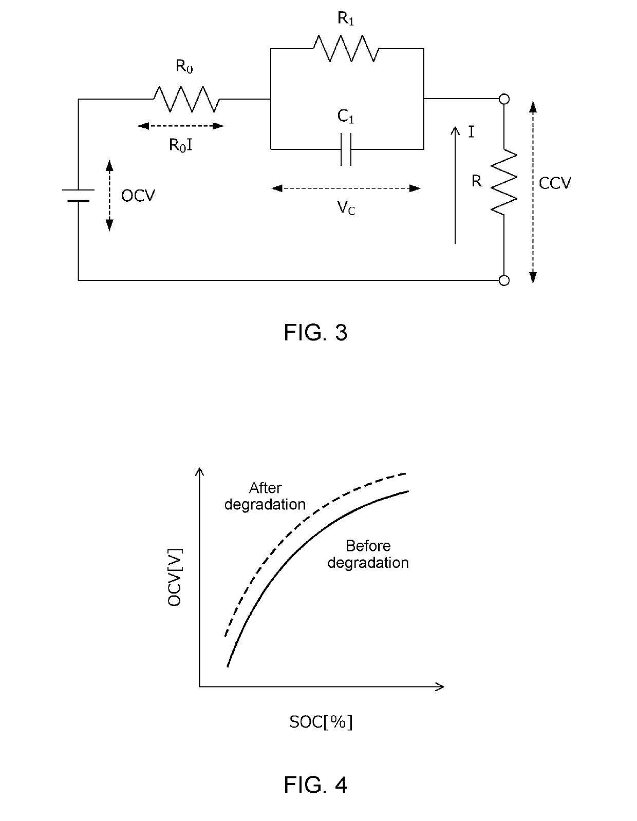
CROSS-REFERENCE TO RELATED APPLICATION[0001]This application claims the priority benefits of Japan application serial no. 2017-198346, filed on Oct. 12, 2017, and serial no. 2017-207204, filed on Oct. 26, 2017. The entirety of each of the above-mentioned patent applications is hereby incorporated by reference herein and made a part of this specification.BACKGROUND OF THE INVENTIONField of the Invention[0002]The invention relates to a battery state estimation method and a battery state estimation device, and, more specifically, to a battery state estimation method and a battery state estimation device for obtaining a correlation characteristic between the charging rate and the open-end voltage of a battery which changes due to degradation.Description of Related Art[0003]The input / output performance of a secondary battery that is mounted on a hybrid electric vehicle (HEV), a plugin hybrid electric vehicle (PHEV), a battery-type electric vehicle (BEV) and the like changes according to ...

Claims


Application Information

Patent Timeline
Patent Type & Authority Applications(United States)
IPC IPC(8): G01R31/392H02J7/00G01R31/36G01R31/382
CPCG01R31/392H02J7/0068G01R31/3648G01R31/382H01M10/44G01R31/3842G01R31/367B60L58/12B60L2240/547B60L2240/549Y02T10/70Y02E60/10H02J7/0049G01R31/3828
Inventor KAWAMURA, MASAYUKI
Owner HONDA MOTOR CO LTD
Why Eureka
Eureka Blog
Learn More